Dodge Durango (HB). Manual - part 912


  Index      Dodge     Dodge Durango (HB) - service repair manual 2005 year


Search            


Content   ..  910  911  912  913   ..


Dodge Durango (HB). Manual - part 912


P0585-SPEED CONTROL SWITCH 1/2 CORRELATION (5.7L) (CONTINUED)

9.

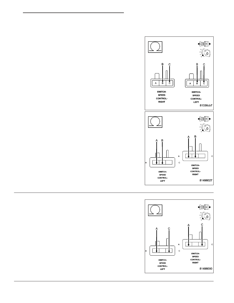
S/C SWITCH SIGNAL CIRCUITS SHORTED TO THE (V937) SWITCH RETURN CIRCUIT

Measure the resistance between the (V937) Switch Return circuit and
both of the (V37) and (V38) S/C Switch Signal circuits in the Speed
Control harness connector.

Is the resistance below 5.0 ohms?

Yes

>> Repair the short between the (V937) Switch Return circuit

and the (V37) or (V38) S/C Switch Signal circuit.

Perform the POWERTRAIN VERIFICATION TEST. (Refer
to 9 - ENGINE - STANDARD PROCEDURE)

No

>> Go To 10

10.

(V37) S/C SWITCH NO.1 SIGNAL CIRCUIT SHORTED TO THE (V38) S/C SWITCH NO.2 SIGNAL
CIRCUIT

Measure the resistance between the (V37) S/C Switch No.1 Signal cir-
cuit and the (V38) S/C Switch No.2 Signal circuit at both Speed Con-
trol harness connectors.

Is the resistance below 100 ohms for each circuit?

Yes

>> Repair the short between the (V38) S/C Switch No.2 Sig-

nal circuit and the (V37) S/C Switch No.1 Signal circuit.

Perform the POWERTRAIN VERIFICATION TEST. (Refer
to 9 - ENGINE - STANDARD PROCEDURE)

No

>> Go To 11

HB

ENGINE ELECTRICAL DIAGNOSTICS

9 - 647

P0585-SPEED CONTROL SWITCH 1/2 CORRELATION (5.7L) (CONTINUED)

11.

S/C SWITCH SIGNAL CIRCUITS SHORTED TO GROUND

Measure the resistance between ground and the (V37) and (V38) S/C
Switch Signal circuits at both Switch harness connectors.

Is the resistance below 100 ohms?

Yes

>> Repair the short to ground in the (V37) or (V38) S/C

Switch Signal circuit.

Perform the POWERTRAIN VERIFICATION TEST. (Refer
to 9 - ENGINE - STANDARD PROCEDURE)

No

>> Go To 12

9 - 648

ENGINE ELECTRICAL DIAGNOSTICS

HB

P0585-SPEED CONTROL SWITCH 1/2 CORRELATION (5.7L) (CONTINUED)

12.

SPEED CONTROL SWITCH VOLTAGE VALUES

Connect the C3 PCM harness connector and the S/C Switch harness connectors.

Allow the engine to idle.

With a scan tool, monitor the S/C Switch voltage readings.

SWITCH POSITION

SWITCH No.1 VOLTAGE VALUE

SWITCH No.2 VOLATGE VALUE

NO SWITCHES PRESSED

4.31 to 4.78 volts

4.31 to 4.78 volts

ON/OFF PRESSED

0.59 and 1.13 volts

3.53 and 3.92 volts

RES/ACCEL PRESSED

3.88 to 4.17 volts

2.04 to 2.47 volts

SET PRESSED

3.16 to 3.56 volts

1.17 to 1.56 volts

COAST PRESSED

2.57 to 2.94 volts

0.77 to 1.09 volts

CANCEL PRESSED

1.59 to 1.99 volts

2.84 to 3.25 volts

Take these same voltage measurements with a voltmeter by back probing the (V37) S/C Switch No.1 Signal circuit
and the (V38) S/C Switch No.2 Signal circuit at the switches.

Compare the voltage readings on the voltmeter to what the scan tool displayed.

Are the voltage readings out of the listed specification and is there less than a 0.2 of a volt difference
between the voltmeter switch values and the scan tool switch values?

Yes

>> Replace the Speed Control Switch.

Perform the POWERTRAIN VERIFICATION TEST. (Refer to 9 - ENGINE - STANDARD PROCEDURE)

No

>> Go To 13

13.

PCM

NOTE: Before continuing, check the PCM harness connector terminals for corrosion, damage, or terminal
push out. Repair as necessary.
Using the schematics as a guide, inspect the wire harness and connectors. Pay particular attention to all Power and
Ground circuits.

Were there any problems found?

Yes

>> Repair as necessary.

Perform the POWERTRAIN VERIFICATION TEST. (Refer to 9 - ENGINE - STANDARD PROCEDURE)

No

>> Replace and program the Powertrain Control Module per Service Information.

Perform the POWERTRAIN VERIFICATION TEST. (Refer to 9 - ENGINE - STANDARD PROCEDURE)

HB

ENGINE ELECTRICAL DIAGNOSTICS

9 - 649

P0586-SPEED CONTROL VENT CONTROL CIRCUIT

9 - 650

ENGINE ELECTRICAL DIAGNOSTICS

HB


Content   ..  910  911  912  913   ..