Dodge Durango (HB). Manual - part 243


  Index      Dodge     Dodge Durango (HB) - service repair manual 2005 year


Search            


Content   ..  241  242  243  244   ..


Dodge Durango (HB). Manual - part 243


INSTALLATION

NOTE: If the ABM needs to be replaced, the rear axle type and tire revolutions per mile must be programed
into the new ABM. For axle type refer to Group 3 Differential and Driveline. For tire revolutions per mile
(Refer to 22 - TIRES/WHEELS/TIRES - SPECIFICATIONS). To program the ABM refer to the Appropriate Diag-
nostic Service Information.

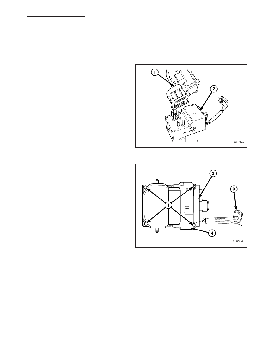
1. Position the module (1) on the HCU (2).

2. Install the mounting screws (1) and tighten to 6

N·m (53 in. lbs).

3. Install the pump electrical connector (3) to the

module (4).

4. Install the HCU to the vehicle (Refer to 5 -

BRAKES/HYDRAULIC/MECHANICAL/HCU
(HYDRAULIC CONTROL UNIT) - INSTALLATION).

COMMUNICATION

DESCRIPTION

The Controller Area Network (CAN) is a serial data bus communication network used for interconnecting numerous
electronic control modules throughout the vehicle in a two-wire multiplexed system. Within this context the term
serial refers to electronic data that is transferred bit by bit, while bus refers to the shared wires through which that
data is transferred. Multiplexing is any system that enables the transmission of multiple messages over a single
channel or circuit. The communication protocol being used is a non-proprietary, open standard adopted from the
Bosch CAN Specification 2.0b and uses an 11-bit message identifier.

There are actually three separate CAN bus systems used in the vehicle. They are designated: the CAN-B, the
CAN-C and the Diagnostic CAN-C. The CAN-B and CAN-C systems provide on-board communication between all
nodes in the vehicle. The CAN-C is the faster of the two systems providing near real-time communication (500
Kbps), but is less fault tolerant than the CAN-B system. The CAN-C is used exclusively for communications
between critical powertrain and chassis nodes. The slower (83.3 Kbps), but more fault tolerant CAN-B system is

HB

ELECTRONIC CONTROL MODULES - SERVICE INFORMATION

8E - 193

used for communications between body and interior nodes. The CAN-B fault tolerance comes from its ability to
revert to a single wire communication mode if there is a fault in the bus wiring.

The Diagnostic CAN-C bus is also capable of 500 Kbps communication, and is sometimes informally referred to as
the CAN-D system to differentiate it from the other high speed CAN-C bus. A central gateway or hub integral to the
Front Control Module (FCM) physically and electrically isolates the three CAN buses from each other and coordi-
nates the bi-directional transfer of messages between the three buses. The FCM is located on the Integrated Power
Module (IPM), which is located in the engine compartment near the battery. The Diagnostic CAN-C is used exclu-
sively for the transmission of diagnostic information between the FCM/gateway and a diagnostic scan tool con-
nected to the industry-standard 16-way Data Link Connector (DLC) located beneath the instrument panel on the
driver side of the vehicle.

Each node is connected in parallel to its CAN-B or CAN-C bus using a two-wire twisted pair. These wires are
wrapped around each other to provide shielding from unwanted electromagnetic induction interfering with the rela-
tively low voltage signals being carried through them. The twisted pairs have between 33 and 50 twists per meter.
While the CAN bus is operating, one of the bus wires will carry a higher voltage and is referred to as the CAN High
or CAN bus (+) wire, while the other bus wire will carry a lower voltage and is referred to as the CAN Low or CAN
bus (–) wire. Each twisted pair terminates at the FCM/gateway.

The added speed of the CAN data bus is many times faster than previous data bus systems. This added speed
facilitates the addition of more electronic control modules or nodes and the incorporation of many new electrical and
electronic features in the vehicle. Like prior data bus systems, the CAN data bus minimizes redundant wiring con-
nections; and, at the same time, reduces wire harness complexity, sensor current loads and controller hardware by
allowing each sensing device to be connected to only one node. Each node reads, then broadcasts its sensor data
over the bus for use by all other nodes requiring that data.

OPERATION

The Controller Area Network (CAN) data bus allows all electronic modules or nodes connected to the bus to share
information with each other. Each node can both send and receive serial data simultaneously. The CAN bus signal
lines have termination through a termination resistor within each node, either dominant or recessive. The serial data
is made up of high and low voltage pulses strung together. Each string of voltage pulses forms a message.

Regardless of whether a message originates from a node on the medium speed CAN-B bus or on the high speed
CAN-C bus, the message structure and layout is the same, which allows the Front Control Module (FCM)/Central
GateWay (sometimes referred to as the FCMCGW) to process and transfer messages between the buses. The pri-
ority of each message is based upon the 11-bit message identifier. Each node uses arbitration to sort the message
priority if two competing messages are attempting to be broadcast at the same time.

The FCM used in the CAN system has more control than a non-CAN FCM. Available options are configured into the
FCM at the assembly plant, but additional options can be added in the field using the diagnostic scan tool. The
configuration settings are stored in non-volatile memory. The FCM also has two 64-bit registers, which register each
of the “as-built” and “currently responding” nodes on the CAN-B and CAN-C buses. The FCM stores a Diagnostic
Trouble Code (DTC) in one of two caches for any detected active or stored faults in the order in which they occur.
One cache stores powertrain (P-Code), chassis (C-Code) and body (B-Code) DTCs, while the second cache is ded-
icated to storing network (U-Code) DTCs.

If there are intermittent or active faults in the CAN network, a diagnostic scan tool connected to the Diagnostic
CAN-C bus through the 16-way Data Link Connector (DLC) may only be able to communicate with the FCM. To aid
in CAN network diagnosis, the FCM will provide CAN-B and CAN-C network status information to the scan tool
using certain diagnostic signals. In addition, the transceiver in each node on the CAN-C bus will identify a “bus off
hardware failure,” while the transceiver in each node on the CAN-B bus will identify a “general bus hardware fail-
ure.” The transceivers for some CAN-B nodes will also identify “bus shorted high,” “bus shorted low,” “bus open” or
“bus shorted together” failures for both CAN-B bus signal wires.

In order to minimize the potential effects of Ignition-Off Draw (IOD), the CAN-B network employs a sleep strategy.
However, a network sleep strategy should not be confused with the sleep strategy of the individual nodes on that
network, as they may differ. For example: The CAN-C bus network is awake only when the ignition switch is in the
On or Start positions; however, the FCM or the Transmission Control Module (TCM), which are on the CAN-C bus,
may still be awake with the ignition switch in the Accessory or Unlock positions. The integrated circuitry of an indi-
vidual node may be capable of processing certain sensor inputs and outputs without the need to utilize network
resources.

The CAN-B bus network remains active until all nodes on that network are ready for sleep. This is determined by
the network using tokens in a manner similar to polling. When the last node that is active on the network is ready

8E - 194

ELECTRONIC CONTROL MODULES - SERVICE INFORMATION

HB

for sleep, and it has already received a token indicating that all other nodes on the bus are ready for sleep, it
broadcasts a “bus sleep acknowledgment” message that causes the network to sleep. Once the CAN-B bus network
is asleep, any node on the bus can awaken it by transmitting a message on the network. The FCM will keep either
the CAN-B or the CAN-C bus awake for a timed interval after it receives a diagnostic message for that bus over the
Diagnostic CAN-C bus.

DATA LINK CONNECTOR

DESCRIPTION

The Data Link Connector (DLC) (2) is a 16-way
molded plastic connector insulator on a dedicated take
out of the instrument panel wire harness. This connec-
tor is located at the lower edge of the instrument
panel, outboard of the steering column. The connector
insulator is retained by integral snap features within a
rectangular cutout in the lower instrument panel rein-
forcement, just below the park brake release handle
(1).

OPERATION

The Data Link Connector (DLC) is an industry-standard 16-way connector that permits the connection of a diag-
nostic scan tool to the Controller Area Network (CAN) for interfacing with, configuring, and retrieving Diagnostic
Trouble Code (DTC) data from the electronic modules that reside on the data bus network of the vehicle.

MODULE-FRONT CONTROL

DESCRIPTION

The Front Control Module (FCM) is a micro controller
based module located in the left front corner of the
engine compartment. The front control module mates
to the power distribution center to form the Integrated
Power Module (IPM). The IPM connects directly to the
battery and provides the primary means of circuit pro-
tection and power distribution for all vehicle electrical
systems. The front control module controls power to
some of these vehicle systems electrical and electro-
mechanical loads based on inputs received from hard
wired switch inputs and data received on the CAN bus
circuit.

HB

ELECTRONIC CONTROL MODULES - SERVICE INFORMATION

8E - 195

OPERATION

As messages are sent over the CAN bus circuit, the Front Control Module (FCM) reads these messages and con-
trols power to some of the vehicles electrical systems by completing the circuit to ground (low side driver) or com-
pleting the circuit to 12 volt power (high side driver). The following functions are controlled by the FCM:

Front turn signals

Stop, turn signal and tail lamps

Front and rear hazard warning lamps

Headlamps

Fog Lamps

Daytime running lamps - if equipped

Horn

Windshield and liftgate wiper and washer systems

Transfer case shifting

Trailer tow wiring output

Rear window defroster power and timing

Air conditioning condenser cooling fan

The FCM provides the following features for the above function:

It provides a illuminated approach feature that turns the headlamps on when the vehicle is unlocked with the
Remote Keyless Entry (RKE) transmitter.

It flashes lamps in response to turn signal, RKE and Vehicle Theft Security System (VTSS) inputs.

It sounds the horn in response to RKE and VTSS inputs.

It turns off the horn in the event of excessively long operation that could otherwise damage the horn.

It turns off the windshield washer motor after 10 seconds of continuous operation to protect the motor.

It minimizes voltage variations to the headlamps to extend bulb life and to equalize the light output from the
lamps, which might otherwise differ due to variations in wiring resistance.

If the headlamps are left on, it automatically turns them off after eight minutes to protect the battery from dis-
charge.It monitors battery voltage and turns off non-essential functions such as the fog lamps, rear window
defogger, and heated seats if necessary to conserve battery power.

It operates the high-beam headlamps at reduced intensity by pulse-width modulation of the power supply to
provide the daytime running lamps.

It provides the variable delay intermittent windshield and liftgate wiper time delay features, and the vehicle
speed sensitive windshield wiper delay variation.

It acts as a link between the CAN bus network for critical powertrain and anti-lock brake systems and the
network for body and interior modules.

DIAGNOSIS AND TESTING

8E - 196

ELECTRONIC CONTROL MODULES - SERVICE INFORMATION

HB


Content   ..  241  242  243  244   ..