Dodge Durango (HB). Manual - part 1159


  Index      Dodge     Dodge Durango (HB) - service repair manual 2005 year


Search            


Content   ..  1157  1158  1159  1160   ..


Dodge Durango (HB). Manual - part 1159


P0713-TRANSMISSION TEMPERATURE SENSOR HIGH (CONTINUED)

5.

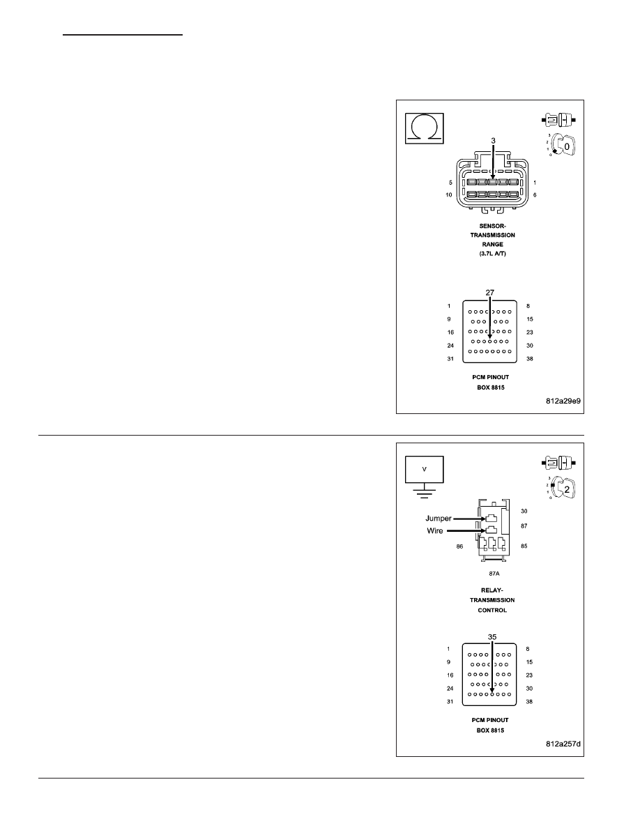
(K900) SENSOR GROUND CIRCUIT OPEN

Disconnect the PCM C2 harness connector

NOTE: Check connectors - Clean/repair as necessary.
Measure the resistance of the (K900) Sensor Ground circuit from the
appropriate terminal of special tool #8815 to the TRS harness connec-
tor.

Is the resistance above 5.0 ohms?

Yes

>> Repair the (K900) Sensor Ground circuit for an open.

Perform 42RLE TRANSMISSION VERIFICATION TEST -
VER 1.

No

>> Go To 6

6.

(T54) TRANSMISSION TEMPERATURE SENSOR SIGNAL
CIRCUIT SHORT TO VOLTAGE

Remove the Transmission Control Relay.

NOTE: Check connectors - Clean/repair as necessary.
Connect a jumper wire between the (A104) Fused B+ circuit and the
(T16) Transmission Control Relay Output circuit in the Transmission
Control Relay connector.

Ignition on, engine not running.

Measure the voltage of the (T54) Transmission Temperature Sensor
Signal circuit in the appropriate terminal of special tool #8815.

Is the voltage above 0.5 volts?

Yes

>> Repair the (T54) Transmission Temperature Sensor Signal

circuit for a short to voltage.

Perform 42RLE TRANSMISSION VERIFICATION TEST -
VER 1.

No

>> Go To 7

HB

AUTOMATIC TRANSMISSION 42RLE - ELECTRICAL DIAGNOSTICS

21 - 41

P0713-TRANSMISSION TEMPERATURE SENSOR HIGH (CONTINUED)

7.

POWERTRAIN CONTROL MODULE

Using the schematics as a guide, inspect the wiring and connectors. Repair as necessary. Pay particular attention
to all power and ground circuits.

If there are no possible causes remaining, view repair.

Repair

Replace the Powertrain Control Module per the Service Information. With the scan tool perform QUICK
LEARN.

Perform 42RLE TRANSMISSION VERIFICATION TEST - VER 1.

8.

INTERMITTENT WIRING AND CONNECTORS

The conditions necessary to set this DTC are not present at this time.

Using the schematics as a guide, inspect the wiring and connectors specific to this circuit.

Wiggle the wires while checking for shorted and open circuits.

With the scan tool, check the EATX DTC EVENT DATA to help identify the conditions in which the DTC was set.

Were there any problems found?

Yes

>> Repair as necessary.

Perform 42RLE TRANSMISSION VERIFICATION TEST - VER 1.

No

>> Test Complete.

21 - 42

AUTOMATIC TRANSMISSION 42RLE - ELECTRICAL DIAGNOSTICS

HB

P0714-TRANSMISSION TEMPERATURE SENSOR INTERMITTENT

HB

AUTOMATIC TRANSMISSION 42RLE - ELECTRICAL DIAGNOSTICS

21 - 43

P0714-TRANSMISSION TEMPERATURE SENSOR INTERMITTENT (CONTINUED)

For the Transmission circuit diagram (Refer to 21 - TRANSMISSION/TRANSAXLE/AUTOMATIC - 42RLE - SCHE-
MATICS AND DIAGRAMS)

For a complete wiring diagram Refer to Section 8W.

When Monitored:
Continuously with the ignition on and engine running.

Set Condition:
The DTC will set when the monitored Temperature Sensor voltage fluctuates or changes abruptly within a pre-
determined period of time.

Possible Causes

TRANSMISSION TEMPERATURE SENSOR

POWERTRAIN CONTROL MODULE

Always perform the Pre-Diagnostic Troubleshooting procedure before proceeding. (Refer to 21 - TRANSMIS-
SION/TRANSAXLE/AUTOMATIC - 42RLE - DIAGNOSIS AND TESTING).

Theory of Operation

The temperature sensor is used to sense the temperature of the transmission fluid. Transmission fluid temperature
can affect shift quality, torque converter operation and when or if some diagnostics are run. A failed temperature
sensor could affect the OBD diagnostics. If a problem occurs in the transmission temperature sensor circuit, trans-
mission temperature will be based on a calculated value.

1.

CHECK TO SEE IF DTC IS CURRENT

With the scan tool, view DTCs.

Is the status Active for this DTC or is the STARTS SINCE SET counter 2 or less?

Yes

>> Go To 2

No

>> Go To 5

2.

PCM AND WIRING

Turn the ignition off to the lock position.

Remove the Starter Relay.

CAUTION: CAUTION: Removal of the Starter Relay is to prevent a Transmission, NO RESPONSE, condition
and disable the starter.
Install the Transmission Simulator, Miller tool #8333 and the Electronic Transmission Adapter kit 8333-1A.

NOTE: Note: Check connectors - Clean/repair as necessary.
Ignition on, engine not running.

With the Transmission Simulator, turn the Input/Output switch to OFF.

With the scan tool , monitor the TRANS TEMP VOLTS while turning the Thermistor Voltage switch to all three posi-
tions on the Transmission Simulator.

Compare the scan tool readings with the numbers listed on the Transmission Simulator.

Do the readings on the Transmission Simulator match a non-fluctuating scan tool reading ± 0.2 volts?

Yes

>> Go To 3

No

>> Go To 4

21 - 44

AUTOMATIC TRANSMISSION 42RLE - ELECTRICAL DIAGNOSTICS

HB


Content   ..  1157  1158  1159  1160   ..