Dodge Durango (HB). Manual - part 1128


  Index      Dodge     Dodge Durango (HB) - service repair manual 2005 year


Search            


Content   ..  1126  1127  1128  1129   ..


Dodge Durango (HB). Manual - part 1128


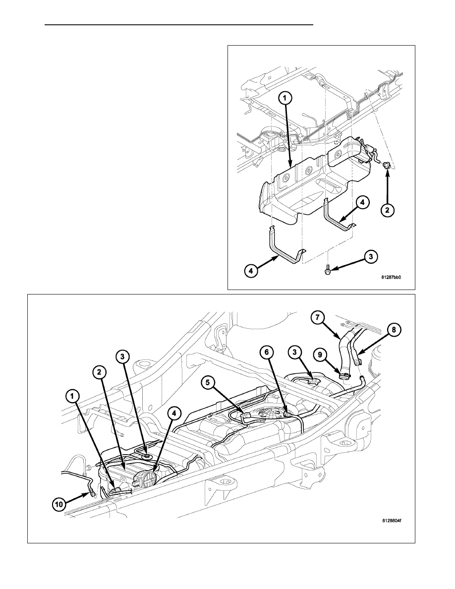
3. Remove two fuel tank strap bolts (3) and remove

both tank support straps (4).

HB

FUEL DELIVERY

14 - 23

4. Carefully lower tank a few inches and disconnect fuel pump module electrical connector (5) at top of tank. To

disconnect electrical connector: Push upward on red colored tab to unlock. Push on black colored tab while
removing connector.

5. Disconnect fuel line (6) at fuel pump module fitting by pressing on tabs at side of quick-connect fitting.

6. Disconnect NVLD, ORVR and EVAP lines (10) at front of tank.

7. Continue to lower tank for removal.

8. If fuel tank is to be replaced, remove fuel pump module from tank. Refer to Fuel Pump Module Removal/Instal-

lation procedures.

INSTALLATION

1. If fuel tank is to be replaced, install fuel pump module into tank. Refer to Fuel Pump Module Removal/Installation

procedures.

2. Position fuel tank to hydraulic jack.

3. Raise tank until positioned near body.

4. Connect EVAP, ORVR and NVLD lines at front of tank.

5. Connect fuel pump module electrical connector at top of tank.

6. Connect fuel line quick-connect fitting to pump module.

7. Continue raising tank until positioned snug to body.

8. Install and position both tank support straps. Install two fuel tank strap bolts and tighten. Refer to Torque Spec-

ifications.

9. Connect rubber fill and vent hoses to fuel tank fittings and tighten hose clamps.

10. If equipped, install fuel tank skid plate.

11. Lower vehicle.

12. Fill fuel tank with fuel.

13. Start engine and check for fuel leaks near top of module.

FILTER-INLET

DESCRIPTION

Refer to Fuel Pump Module for information.

REGULATOR-FUEL PRESSURE

DESCRIPTION

Refer to Fuel Pump Module for information.

FILTER-FUEL

DESCRIPTION

Refer to Fuel Pump Module for information.

14 - 24

FUEL DELIVERY

HB

FUEL INJECTION

TABLE OF CONTENTS

page

page

PEDAL-ACCELERATOR (EXC. CODE XAP)

REMOVAL

. . . . . . . . . . . . . . . . . . . . . . . . . . . . . 26

INSTALLATION

. . . . . . . . . . . . . . . . . . . . . . . . . 27

SENSOR-ACCELERATOR PEDAL POSIT

DESCRIPTION

. . . . . . . . . . . . . . . . . . . . . . . . . 28

OPERATION

. . . . . . . . . . . . . . . . . . . . . . . . . . . 28

REMOVAL

. . . . . . . . . . . . . . . . . . . . . . . . . . . . . 28

INSTALLATION

. . . . . . . . . . . . . . . . . . . . . . . . . 28

SENSOR-CRANKSHAFT POSITION

DESCRIPTION

. . . . . . . . . . . . . . . . . . . . . . . . . 28

OPERATION

. . . . . . . . . . . . . . . . . . . . . . . . . . . 29

REMOVAL

. . . . . . . . . . . . . . . . . . . . . . . . . . . . . 30

INSTALLATION

. . . . . . . . . . . . . . . . . . . . . . . . . 31

INJECTOR-FUEL

DESCRIPTION

. . . . . . . . . . . . . . . . . . . . . . . . . 32

OPERATION - FUEL INJECTOR

. . . . . . . . . . . . 33

REMOVAL

. . . . . . . . . . . . . . . . . . . . . . . . . . . . . 33

INSTALLATION

. . . . . . . . . . . . . . . . . . . . . . . . . 33

RELAY-FUEL PUMP

DESCRIPTION

. . . . . . . . . . . . . . . . . . . . . . . . . 34

OPERATION

. . . . . . . . . . . . . . . . . . . . . . . . . . . 34

REMOVAL

. . . . . . . . . . . . . . . . . . . . . . . . . . . . . 34

INSTALLATION

. . . . . . . . . . . . . . . . . . . . . . . . . 34

MOTOR-IDLE AIR CONTROL

DESCRIPTION

. . . . . . . . . . . . . . . . . . . . . . . . . 34

OPERATION

. . . . . . . . . . . . . . . . . . . . . . . . . . . 34

REMOVAL

. . . . . . . . . . . . . . . . . . . . . . . . . . . . . 36

INSTALLATION

. . . . . . . . . . . . . . . . . . . . . . . . . 37

SENSOR-INTAKE AIR TEMPERATURE

DESCRIPTION

. . . . . . . . . . . . . . . . . . . . . . . . . 37

OPERATION

. . . . . . . . . . . . . . . . . . . . . . . . . . . 37

REMOVAL

. . . . . . . . . . . . . . . . . . . . . . . . . . . . . 38

INSTALLATION

. . . . . . . . . . . . . . . . . . . . . . . . . 40

SENSOR-MAP

DESCRIPTION

. . . . . . . . . . . . . . . . . . . . . . . . . 40

OPERATION

. . . . . . . . . . . . . . . . . . . . . . . . . . . 41

REMOVAL

. . . . . . . . . . . . . . . . . . . . . . . . . . . . . 42

INSTALLATION

. . . . . . . . . . . . . . . . . . . . . . . . . 44

SENSOR-OXYGEN

DESCRIPTION

. . . . . . . . . . . . . . . . . . . . . . . . . 45

REMOVAL

. . . . . . . . . . . . . . . . . . . . . . . . . . . . . 45

INSTALLATION

. . . . . . . . . . . . . . . . . . . . . . . . . 46

THROTTLE BODY

DESCRIPTION

. . . . . . . . . . . . . . . . . . . . . . . . . 46

OPERATION

. . . . . . . . . . . . . . . . . . . . . . . . . . . 46

REMOVAL

. . . . . . . . . . . . . . . . . . . . . . . . . . . . . 47

INSTALLATION

. . . . . . . . . . . . . . . . . . . . . . . . . 49

CABLE-THROTTLE CONTROL

REMOVAL

. . . . . . . . . . . . . . . . . . . . . . . . . . . . . 50

INSTALLATION

. . . . . . . . . . . . . . . . . . . . . . . . . 53

SENSOR-THROTTLE POSITION

DESCRIPTION

. . . . . . . . . . . . . . . . . . . . . . . . . 56

OPERATION

. . . . . . . . . . . . . . . . . . . . . . . . . . . 56

REMOVAL

. . . . . . . . . . . . . . . . . . . . . . . . . . . . . 56

INSTALLATION

. . . . . . . . . . . . . . . . . . . . . . . . . 58

HB

FUEL INJECTION

14 - 25

PEDAL-ACCELERATOR (EXC. CODE XAP)

REMOVAL

Without APPS

The following procedure applies only to vehicles with-
out the Adjustable Pedal Package (code XAP). It also
applies to vehicles not equipped with an accelerator
pedal position sensor.

The accelerator pedal is serviced as a complete
assembly including the bracket.

The accelerator cable is connected to the upper part
of the accelerator pedal arm by a plastic retainer (clip)
(7). This plastic retainer snaps into the top of the
accelerator pedal arm.

1. From inside the vehicle, hold up accelerator pedal.

Remove plastic cable retainer (clip) (7) and throttle
cable core wire from upper end of accelerator
pedal arm (6). Plastic cable retainer (clip) snaps
into pedal arm.

2. Remove two accelerator pedal mounting bracket

nuts (5). Remove accelerator pedal assembly (4).

With APPS

The following procedure applies only to vehicles with-
out the Adjustable Pedal Package (code XAP). It also
applies to vehicles equipped with an accelerator
pedal position sensor (6).

The accelerator pedal (4) is serviced as a complete
assembly including the bracket.

1. Disconnect electrical connector (1) at APPS (6).

2. Remove two accelerator pedal mounting bracket

nuts (5). Remove accelerator pedal assembly (4).

14 - 26

FUEL INJECTION

HB


Content   ..  1126  1127  1128  1129   ..