Dodge Durango (HB). Manual - part 1059


  Index      Dodge     Dodge Durango (HB) - service repair manual 2005 year


Search            


Content   ..  1057  1058  1059  1060   ..


Dodge Durango (HB). Manual - part 1059


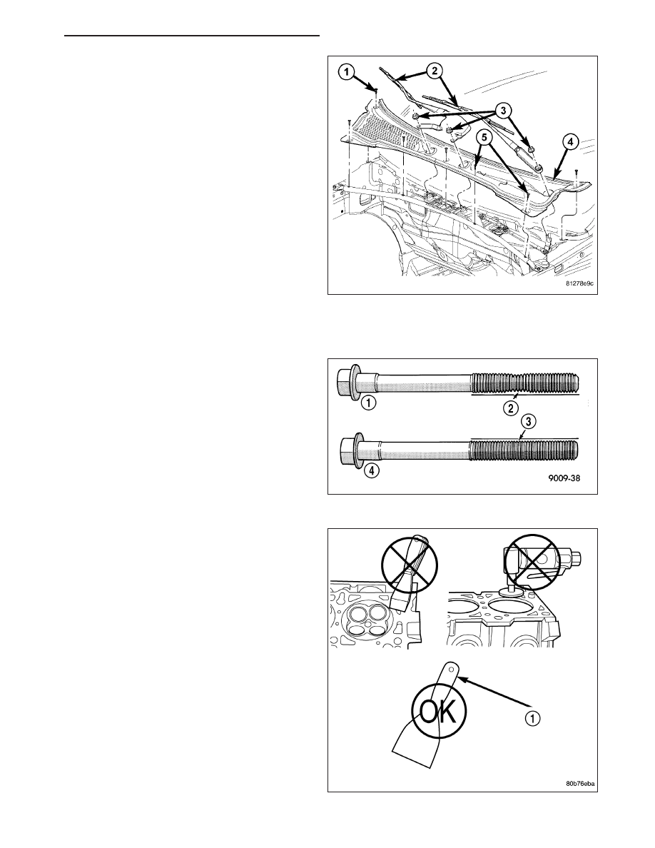
20. Install the cowl grille (4).

21. Refill the cooling system (Refer to 7 - COOLING -

STANDARD PROCEDURE).

22. Connect the negative cable to the battery.

23. Start the engine and check for leaks.

INSTALLATION - RIGHT CYLINDER HEAD

NOTE: The cylinder head bolts are tightened using
a torque plus angle procedure. The bolts must be
examined

BEFORE

reuse.

If

the

threads

are

necked down (2) the bolts should be replaced.

Necking (2) can be checked by holding a straight
edge against the threads. If all the threads do not con-
tact the scale (2), the bolt should be replaced.

CAUTION: When cleaning cylinder head and cylin-
der block surfaces, DO NOT use a metal scraper
because the surfaces could be cut or ground. Use
only a wooden or plastic scraper (1).

HB

ENGINE - 4.7L SERVICE INFORMATION

9 - 1235

1. Clean the cylinder head and cylinder block mating surfaces.

2. Position the new cylinder head gasket on the locat-

ing dowels.

CAUTION: When installing cylinder head, use care
not damage the tensioner arm or the guide arm.

3. Position the cylinder head onto the cylinder block.

Make sure the cylinder head seats fully over the
locating dowels.

NOTE: The four smaller cylinder head mounting
bolts require sealant to be added to them before
installing. Failure to do so may cause leaks.

4. Lubricate the cylinder head bolt threads with clean

engine oil and install the ten M10 bolts.

5. Coat the four M8 cylinder head bolts with Mopar

T

Lock and Seal Adhesive then install the bolts.

NOTE: The cylinder head bolts are tightened using an angle torque procedure, however, the bolts are not a
torque-to-yield design.

6. Tighten the bolts in sequence using the following steps and torque values:

Step 1: Tighten bolts 1–10, 20 N·m (15 ft. lbs.).

Step 2: Tighten bolts 1–10, 47 N·m (35 ft. lbs.). Tighten bolts 11–14, 25 N·m (18 ft. lbs.).

Step 3: Tighten bolts 1–10, 90 degrees. Tighten bolts 11–14, 30 N·m (22 ft. lbs.).

7. Position the secondary chain onto the camshaft drive gear, making sure one marked chain link is on either side

of the V8 mark on the gear (2) and position the gear onto the camshaft.

8. Install the camshaft drive gear retaining bolt.

9. Install the right side secondary chain guide (Refer to 9 - ENGINE/VALVE TIMING/TIMING BELT / CHAIN COV-

ER(S) - INSTALLATION).

9 - 1236

ENGINE - 4.7L SERVICE INFORMATION

HB

10. Install the right side cylinder head access plug (1).

11. Re-set and install the right side secondary chain

tensioner.

12. Remove Special Tool 8515 (6).

13. Install the timing chain cover (Refer to 9 -

ENGINE/VALVE TIMING/TIMING BELT / CHAIN
COVER(S) - INSTALLATION).

14. Install the crankshaft damper (Refer to 9 -

ENGINE/ENGINE BLOCK/VIBRATION DAMPER -
INSTALLATION).

15. Install accessory drive belt (Refer to 7 - COOL-

ING/ACCESSORY

DRIVE/DRIVE

BELTS

-

INSTALLATION).

16. Install the fan shroud.

17. Install the cylinder head cover (1) (Refer to 9 -

ENGINE/CYLINDER

HEAD/CYLINDER

HEAD

COVER(S) - INSTALLATION).

18. Install the intake manifold (Refer to 9 - ENGINE/

MANIFOLDS/INTAKE MANIFOLD - INSTALLA-
TION).

19. Install the exhaust pipe onto the right exhaust

manifold.

20. Install oil fill housing onto cylinder head.

HB

ENGINE - 4.7L SERVICE INFORMATION

9 - 1237

21. Install the cowl grille (4).

22. Refill the cooling system (Refer to 7 - COOLING -

STANDARD PROCEDURE).

23. Reconnect battery negative cable.

24. Start the engine and check for leaks.

CAMSHAFT - LEFT

DESCRIPTION

The camshafts consist of powdered metal steel lobes which are sinter-bonded to a steel tube. A steel post or nose
piece is friction-welded to the steel camshaft tube. Five bearing journals are machined into the camshaft, four on the
steel tube and one on the steel nose piece. Camshaft end play is controlled by two thrust walls that border the nose
piece journal. Engine oil enters the hollow camshafts at the third journal and lubricates every intake lobe rocker
through a drilled passage in the intake lobe.

REMOVAL

1. Remove cylinder head cover (1) (Refer to 9 -

ENGINE/CYLINDER

HEAD/CYLINDER

HEAD

COVER(S) - REMOVAL).

9 - 1238

ENGINE - 4.7L SERVICE INFORMATION

HB


Content   ..  1057  1058  1059  1060   ..