Dodge Durango (HB). Manual - part 96
C102B–RIGHT REAR WHEEL SPEED SENSOR CIRCUIT (CONTINUED)
7.
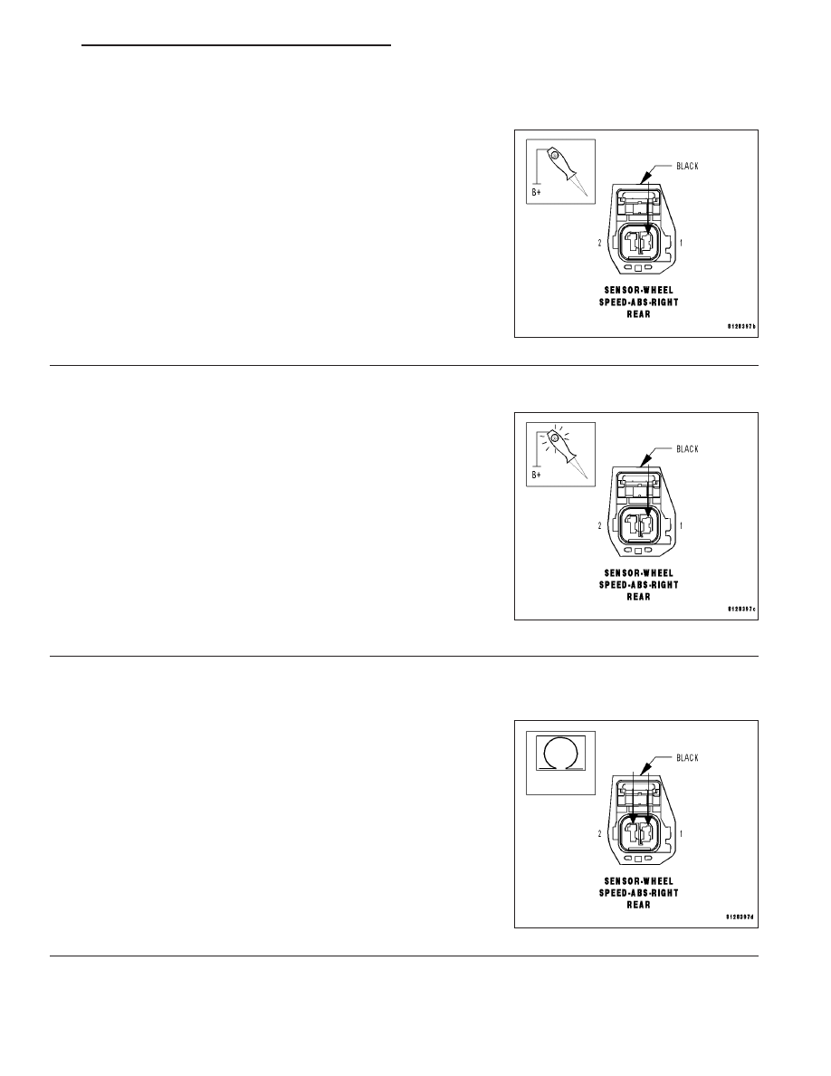
CHECK (B1) RIGHT REAR WSS SIGNAL CIRCUIT SHORT TO GROUND
Turn the ignition off.
Disconnect the Anti-Lock Brake Module harness connector.
Disconnect the Right Rear WSS harness connector.
Using a 12-volt test light connected to 12-volts, probe the (B1) Right
Rear WSS Signal circuit.
Does the test light illuminate brightly?
Yes
>> Repair the (B1) Right Rear WSS Signal circuit for a short
to ground.
Perform ABS VERIFICATION TEST - VER 1.
No
>> Go To 8
8.
CHECK (B1) RIGHT REAR WSS SIGNAL CIRCUIT OPEN
Turn the ignition off.
Disconnect the Anti-Lock Brake Module harness connector.
Disconnect the Right Rear WSS harness connector.
Connect a jumper wire between the (B1) Right Rear WSS Signal cir-
cuit and ground.
Using a 12-volt test light connected to 12-volts, probe the (B1) Right
Rear WSS Signal circuit.
Does the test light illuminate brightly?
Yes
>> Go To 9
No
>> Repair the (B1) Right Rear WSS Signal circuit for an
open.
Perform ABS VERIFICATION TEST - VER 1.
9.
CHECK (B1) RIGHT REAR WSS SIGNAL CIRCUIT AND (B2) RIGHT REAR WSS SUPPLY CIRCUIT SHORT
TOGETHER
Turn the ignition off.
Disconnect the Anti-Lock Brake Module harness connector.
Disconnect the Right Rear WSS harness connector.
Measure the resistance between the (B1) Right Rear WSS Signal cir-
cuit and the (B2) Right Rear WSS Supply circuit.
Is the resistance above 5.0 ohms?
Yes
>> Go To 10
No
>> Repair the (B1) Right Rear WSS Signal circuit and the
(B2) Right Rear WSS Supply circuit for a short together.
Perform ABS VERIFICATION TEST - VER 1.
HB
BRAKES - ABS ELECTRICAL DIAGNOSTICS
5 - 163