Dodge Durango (DN). Manual - part 450
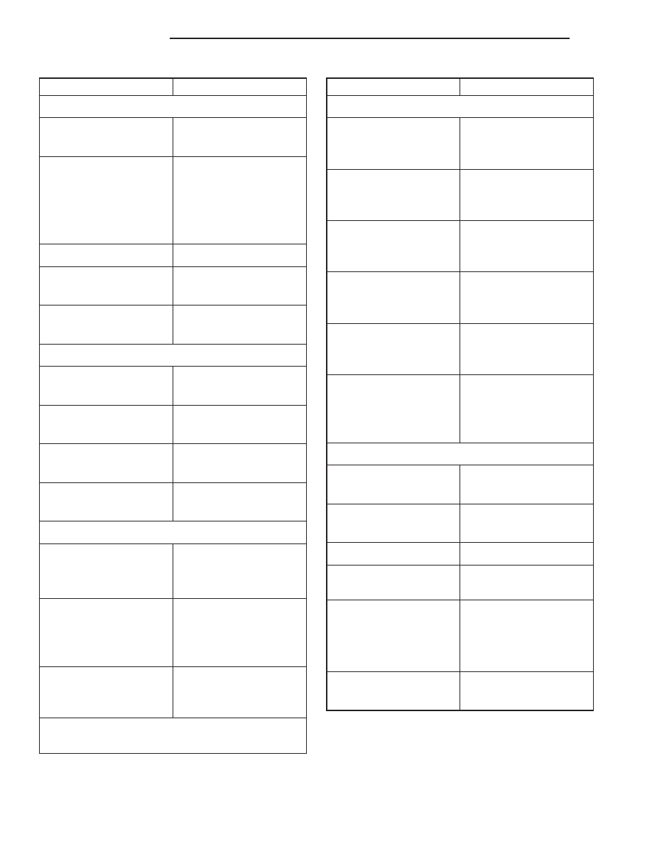
DESCRIPTION
SPECIFICATION
VALVE SPRINGS
Free Length
49.962 mm
(1.967 in.)
Spring Tension
valve closed
378 N @ 41.66 mm
(85 lbs. @ 1.64 in.)
valve open
890 N @ 30.89 mm
(200 lbs. @ 1.212 in.)
Number of Coils
6.5
Installed Height
41.66 mm
(1.64 in.)
Wire Diameter
4.50 mm
(0.177 in.)
HYDRAULIC TAPPETS
Body Diameter
22.949 – 22.962 mm
(0.9035 – 0.9040 in.)
Clearance (to bore)
0.0279 – 0.0610 mm
(0.0011 – 0.0024 in.)
Dry Lash
1.524 – 5.334 mm
(0.060 – 0.210 in.)
Push Rod Length
175.64 – 176.15 mm
(6.915 – 6.935 in.)
OIL PRESSURE
Curb Idle (Min.*)
41.4 kPa (6 psi)
@ 3000 rpm
207 – 552 kPa
(30 – 80 psi)
Oil Pressure Bypass
Valve
Setting
62 – 103 kPa
(9 – 15 psi)
Switch Actuating
Pressure
34.5 – 48.3 kPa
(5 – 7 psi)
* If oil pressure is zero at curb idle, DO NOT RUN
ENGINE.
DESCRIPTION
SPECIFICATION
OIL PUMP
Clearance over Rotors
(Max.)
0.0381 mm
(0.0015 in.)
Inner Rotor Thickness
(Min.)
20.955 mm
(0.825 in.)
Outer Rotor Clearance
(Max.)
0.3556 mm
(0.014 in.)
Outer Rotor Diameter
(Min.)
62.7126 mm
(2.469 in.)
Outer Rotor Thickness
(Min.)
20.955 mm
(0.825 in.)
Tip Clearance between
Rotors
(Max.)
0.2032 mm
(0.008 in.)
PISTONS
Clearance at Top of Skirt
0.013 – 0.038 mm
(0.0005 – 0.0015 in.)
Land Clearance (Diam.)
0.635 – 1.016 mm
(0.025 – 0.040 in.)
Piston Length
86.360 mm (3.40 in.)
Piston Ring Groove
Depth
Groove #1&2
4.572 – 4.826 mm
(0.180 – 0.190 in.)
Groove #3
3.810 – 4.064 mm
(0.150 – 0.160 in.)
Weight
592.6 – 596.6 grams
(20.90 – 21.04 oz.)
9 - 130
5.2L ENGINE
DN
SPECIFICATIONS (Continued)