Dodge Durango (DN). Manual - part 440
 

  Index      Dodge     Dodge Durango (DN) - service repair manual 2000 year


Search            


Content   ..  438  439  440  441   ..


Dodge Durango (DN). Manual - part 440


CRANKSHAFT MAIN BEARINGS

DESCRIPTION

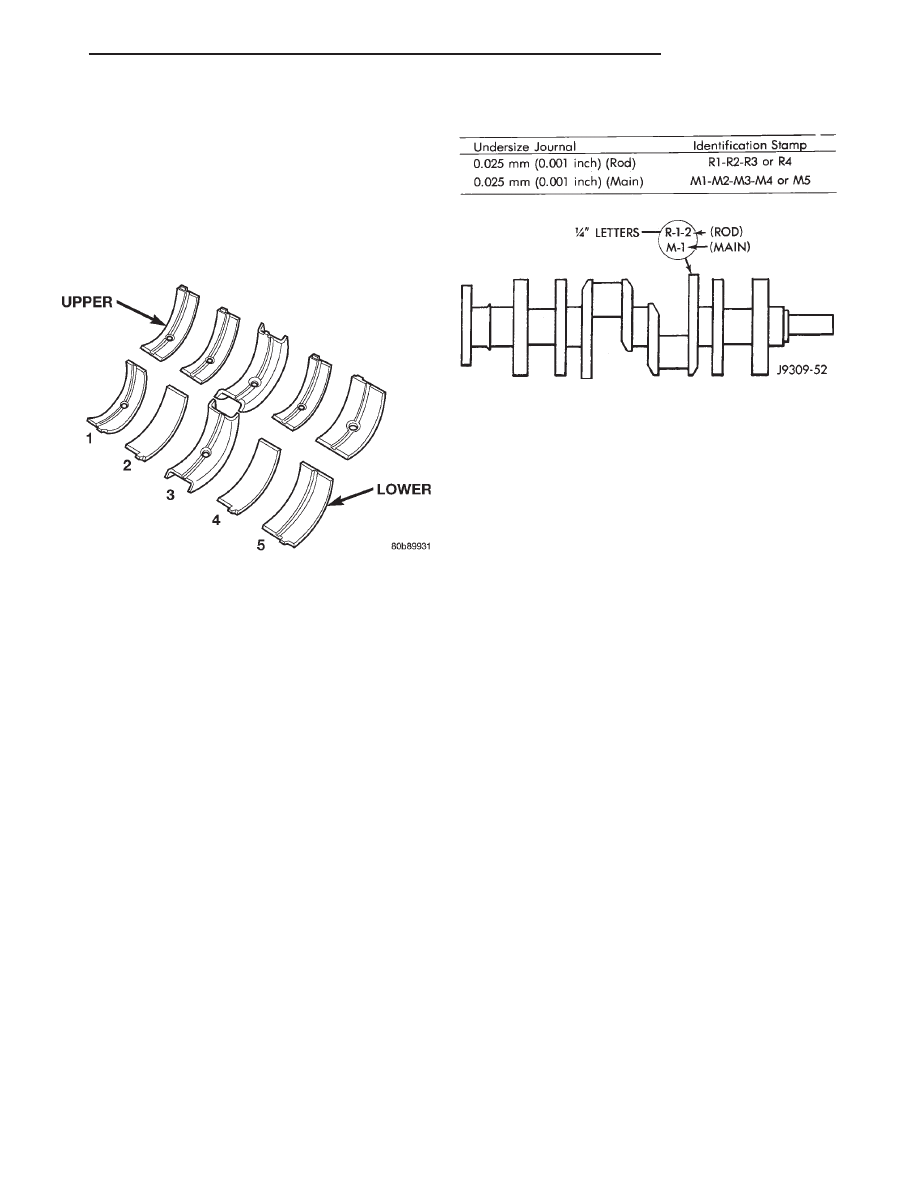
Main bearings are located in the cylinder block.

One half of the main bearing is located in the crank-
shaft main bore the other half of the matching bear-
ing is located in the main bearing cap (Fig. 9). There
are five main bearings. Number three main bearing
is flanged, this flange controls crankshaft thrust.

OPERATION

The main bearings encircle the crankshaft main

bearing journals, this aligns the crankshaft to the
centerline of the engine and allows the crankshaft to
turn without wobbling or shaking therefore eliminat-
ing vibration. The main bearings are available in
standard and undersizes.

CRANKSHAFT

DESCRIPTION

The crankshaft is of a cast nodular steel splayed

type design, with five main bearing journals. The
crankshaft is located at the bottom of the engine
block and is held in place with five main bearing
caps. The number 3 counterweight is the location for
journal size identification (Fig. 10).

OPERATION

The crankshaft transfers force generated by com-

bustion within the cylinder bores to the flywheel or
flexplate.

SERVICE PROCEDURES

FORM-IN-PLACE GASKETS

There are several places where form-in-place gas-

kets are used on the engine. DO NOT use form-in-

place gasket material unless specified. Care
must be taken when applying form-in-place gaskets.
Bead size, continuity and location are of great impor-
tance. Too thin a bead can result in leakage while too
much can result in spill-over. A continuous bead of
the proper width is essential to obtain a leak-free
joint.

Two types of form-in-place gasket materials are

used in the engine area (Mopar Silicone Rubber
Adhesive Sealant and Mopar Gasket Maker). Each
have different properties and cannot be used inter-
changeably.

MOPAR SILICONE RUBBER ADHESIVE SEALANT

Mopar Silicone Rubber Adhesive Sealant, normally

black in color, is available in 3 ounce tubes. Moisture
in the air causes the sealant material to cure. This
material is normally used on flexible metal flanges.
It has a shelf life of a year and will not properly cure
if over aged. Always inspect the package for the expi-
ration date before use.

MOPAR GASKET MAKER

Mopar Gasket Maker, normally red in color, is

available in 6 cc tubes. This anaerobic type gasket
material cures in the absence of air when squeezed
between smooth machined metallic surfaces. It will
not cure if left in the uncovered tube. DO NOT use
on flexible metal flanges.

SURFACE PREPARATION

Parts assembled with form-in-place gaskets may be

disassembled

without

unusual

effort.

In

some

instances, it may be necessary to lightly tap the part
with a mallet or other suitable tool to break the seal
between the mating surfaces. A flat gasket scraper
may also be lightly tapped into the joint but care
must be taken not to damage the mating surfaces.

Fig. 9 Main Bearing Orientation

Fig. 10 Crankshaft with Journal Size Identification

DN

5.2L ENGINE

9 - 91

DESCRIPTION AND OPERATION (Continued)

Scrape or wire brush all gasket surfaces to remove

all loose material. Inspect stamped parts to ensure
gasket rails are flat. Flatten rails with a hammer on
a flat plate, if required. Gasket surfaces must be free
of oil and dirt. Make sure the old gasket material is
removed from blind attaching holes.

GASKET APPLICATION

Assembling parts using a form-in-place gasket

requires care.

Mopar Silicone Rubber Adhesive Sealant should be

applied in a continuous bead approximately 3 mm
(0.12 inch) in diameter. All mounting holes must be
circled. For corner sealing, a 3 or 6 mm (1/8 or 1/4
inch) drop is placed in the center of the gasket con-
tact area. Uncured sealant may be removed with a
shop towel. Components should be torqued in place
while the sealant is still wet to the touch (within 10
minutes). The use of a locating dowel is recom-
mended during assembly to prevent smearing the
material off location.

Mopar Gasket Maker should be applied sparingly

to one gasket surface. The sealant diameter should
be 1.00 mm (0.04 inch) or less. Be certain the mate-
rial surrounds each mounting hole. Excess material
can easily be wiped off. Components should be
torqued in place within 15 minutes. The use of a
locating dowel is recommended during assembly to
prevent smearing the material off location.

ENGINE PERFORMANCE

It is important that the vehicle is operating to its

optimum performance level to maintain fuel economy
and the lowest emission levels. If vehicle is not oper-
ating to these standards, refer to Engine Diagnosis
outlined in this section. The following procedures can
assist in achieving the proper engine diagnosis.

(1) Test cranking amperage draw. Refer to Electri-

cal Group 8B, Cold Cranking Test.

(2) Check intake manifold bolt torque.
(3) Perform cylinder compression test. Refer to

Cylinder Compression Pressure Test in the Engine
Diagnosis area of this section.

(4) Clean or replace spark plugs as necessary and

adjust gap as specified in Electrical Group 8D.
Tighten to specifications.

(5) Test resistance of spark plug cables. Refer to

Electrical Group 8D, Spark Plug Cables.

(6) Inspect the primary wires. Test coil output volt-

age and primary resistance. Replace parts as neces-
sary. Refer to Electrical Group 8D, for specifications.

(7) Test fuel pump for pressure. Refer to Group 14,

Fuel System Specifications.

(8) The air filter elements should be replaced as

specified in Lubrication and Maintenance, Group 0.

(9) Inspect crankcase ventilation system as out

lined in Group 0, Lubrication and Maintenance. For
emission controls see Group 25, Emission Controls
for service procedures.

(10) Road test vehicle as a final test.

ENGINE OIL

WARNING: NEW OR USED ENGINE OIL CAN BE
IRRITATING TO THE SKIN. AVOID PROLONGED OR
REPEATED SKIN CONTACT WITH ENGINE OIL.
CONTAMINANTS IN USED ENGINE OIL, CAUSED BY
INTERNAL COMBUSTION, CAN BE HAZARDOUS TO
YOUR HEALTH. THOROUGHLY WASH EXPOSED
SKIN WITH SOAP AND WATER. DO NOT WASH
SKIN WITH GASOLINE, DIESEL FUEL, THINNER, OR
SOLVENTS, HEALTH PROBLEMS CAN RESULT. DO
NOT POLLUTE, DISPOSE OF USED ENGINE OIL
PROPERLY.

ENGINE OIL SPECIFICATION

CAUTION: Do not use non-detergent or straight
mineral oil when adding or changing crankcase
lubricant. Engine failure can result.

API SERVICE GRADE CERTIFIED

In gasoline engines, use an engine oil that is API

Service Grade Certified (Fig. 11). Standard engine oil
identification notations have been adopted to aid in
the proper selection of engine oil. The identifying
notations are located on the label of engine oil plastic
bottles and the top of engine oil cans. MOPAR only
provides engine oil that conforms to this certification.

SAE VISCOSITY

An SAE viscosity grade is used to specify the vis-

cosity of engine oil. SAE 10W-30 specifies a multiple
viscosity engine oil. These are specified with a dual
SAE viscosity grade which indicates the cold-to-hot
temperature viscosity range. When choosing an
engine oil, consider the range of temperatures the
vehicle will be operated in before the next oil change.
Select an engine oil that is best suited to your area’s

Fig. 11 Engine Oil Container Standard Notations

9 - 92

5.2L ENGINE

DN

SERVICE PROCEDURES (Continued)

particular ambient temperature range and variation
(Fig. 12).

ENERGY CONSERVING OIL

An Energy Conserving type oil is recommended for

gasoline engines. The designation of ENERGY CON-
SERVING is located on the label of an engine oil con-
tainer.

OIL LEVEL INDICATOR (DIPSTICK)

The engine oil level indicator is located at the right

front of the engine, left of the generator on 5.2L
engines (Fig. 13).

CRANKCASE OIL LEVEL INSPECTION

CAUTION: Do not overfill crankcase with engine oil,
oil foaming and oil pressure loss can result.

To ensure proper lubrication of an engine, the

engine oil must be maintained at an acceptable level.
The acceptable levels are indicated between the ADD
and SAFE marks on the engine oil dipstick.

(1) Position vehicle on level surface.
(2) With engine OFF, allow approximately ten min-

utes for oil to settle to bottom of crankcase, remove
engine oil dipstick.

(3) Wipe dipstick clean.
(4) Install dipstick and verify it is seated in the

tube.

(5) Remove dipstick, with handle held above the

tip, take oil level reading.

(6) Add oil only if level is below the ADD mark on

dipstick.

ENGINE OIL CHANGE

Change engine oil at mileage and time intervals

described in the Maintenance Schedule. This infor-
mation can be found in your owner’s manual.

TO CHANGE ENGINE OIL

Run engine until achieving normal operating tem-

perature.

(1) Position the vehicle on a level surface and turn

engine off.

(2) Hoist and support vehicle on safety stands.

Refer to Hoisting and Jacking Recommendations.

(3) Remove oil fill cap.
(4) Place a suitable drain pan under crankcase

drain.

(5) Remove drain plug from crankcase and allow

oil to drain into pan. Inspect drain plug threads for
stretching or other damage. Replace drain plug and
gasket if damaged.

(6) Install drain plug in crankcase.
(7) Lower vehicle and fill crankcase with specified

type and amount of engine oil described in this sec-
tion.

(8) Install oil fill cap.
(9) Start engine and inspect for leaks.
(10) Stop engine and inspect oil level.

ENGINE OIL FILTER CHANGE

FILTER SPECIFICATION

All engines are equipped with a high quality full-

flow, disposable type oil filter. DaimlerChrysler Cor-
poration recommends a Mopar or equivalent oil filter
be used.

OIL FILTER REMOVAL

(1) Position a drain pan under the oil filter.
(2) Using a suitable oil filter wrench loosen filter.
(3) Rotate the oil filter counterclockwise to remove

it from the cylinder block oil filter boss (Fig. 14).

Fig. 12 Temperature/Engine Oil Viscosity

Recommendation

Fig. 13 Engine Oil Dipstick Location—5.2L Engines

1 – CYLINDER HEAD COVER
2 – ENGINE OIL FILL-HOLE CAP
3 – DIPSTICK
4 – ENGINE OIL FILTER
5 – FILTER BOSS

DN

5.2L ENGINE

9 - 93

SERVICE PROCEDURES (Continued)

(4) When filter separates from adapter nipple, tip

gasket end upward to minimize oil spill. Remove fil-
ter from vehicle.

(5) With a wiping cloth, clean the gasket sealing

surface (Fig. 15) of oil and grime.

OIL FILTER INSTALLATION

(1) Lightly lubricate oil filter gasket with engine

oil or chassis grease.

(2) Thread filter onto adapter nipple. When gasket

makes contact with sealing surface, (Fig. 15) hand
tighten filter one full turn, do not over tighten.

(3) Add oil, verify crankcase oil level and start

engine. Inspect for oil leaks.

REPAIR DAMAGED OR WORN THREADS

CAUTION: Be sure that the tapped holes maintain
the original center line.

Damaged or worn threads can be repaired. Essen-

tially, this repair consists of:

• Drilling out worn or damaged threads.

• Tapping the hole with a special Heli-Coil Tap, or

equivalent.

• Installing an insert into the tapped hole to bring

the hole back to its original thread size.

CYLINDER BORE—HONING

Before honing, stuff plenty of clean shop towels

under the bores and over the crankshaft to keep
abrasive materials from entering the crankshaft
area.

(1) Used carefully, the Cylinder Bore Sizing Hone

C-823, equipped with 220 grit stones, is the best tool
for this job. In addition to deglazing, it will reduce
taper and out-of-round, as well as removing light
scuffing, scoring and scratches. Usually, a few strokes
will clean up a bore and maintain the required lim-
its.

CAUTION: DO NOT use rigid type hones to remove
cylinder wall glaze.

(2) Deglazing of the cylinder walls may be done if

the cylinder bore is straight and round. Use a cylin-
der surfacing hone, Honing Tool C-3501, equipped
with 280 grit stones (C-3501-3810). about 20-60
strokes, depending on the bore condition, will be suf-
ficient to provide a satisfactory surface. Using honing
oil C-3501-3880, or a light honing oil, available from
major oil distributors.

CAUTION: DO NOT use engine or transmission oil,
mineral spirits, or kerosene.

(3) Honing should be done by moving the hone up

and down fast enough to get a crosshatch pattern.
The hone marks should INTERSECT at 50° to 60°
for proper seating of rings (Fig. 16).

Fig. 14 Oil Filter Removal—Typical

1 – ENGINE OIL FILTER
2 – OIL FILTER WRENCH

Fig. 15 Oil Filter Sealing Surface—Typical

1 – SEALING SURFACE
2 – RUBBER GASKET
3 – OIL FILTER

Fig. 16 Cylinder Bore Crosshatch Pattern

1 – CROSSHATCH PATTERN
2 – INTERSECT ANGLE

9 - 94

5.2L ENGINE

DN

SERVICE PROCEDURES (Continued)


Content   ..  438  439  440  441   ..