Dodge Durango (DN). Manual - part 424
(9) Repeat the Plastigage measurement to verify
your bearing selection prior to final assembly.
(10) Once you have selected the proper insert,
install the insert and cap. Tighten the connecting rod
bolts to 27 N·m (20 ft. lbs.) plus a 90° turn.
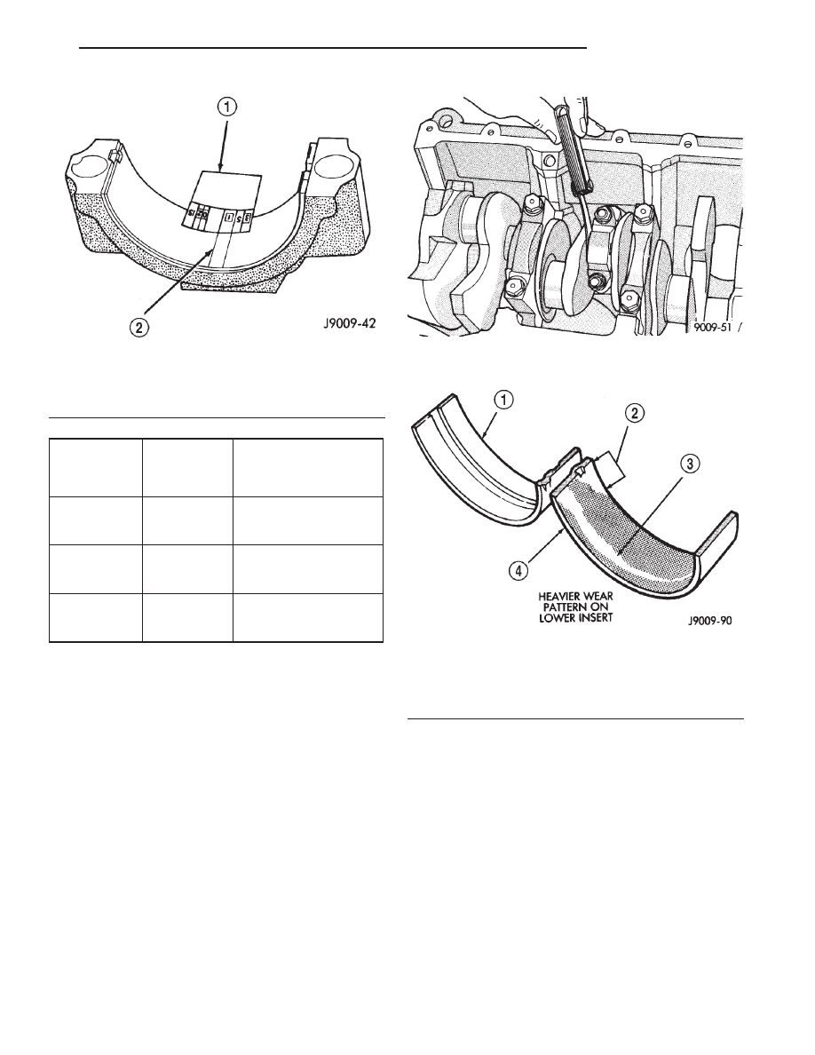
Slide snug-fitting feeler gauge between the con-
necting rod and crankshaft journal flange (Fig. 30).
Refer to Engine Specifications for the proper clear-
ance. Replace the connecting rod if the side clearance
is not within specification.
CRANKSHAFT MAIN BEARINGS
INSPECTION
Wipe the inserts clean and inspect for abnormal
wear patterns and for metal or other foreign material
imbedded in the lining. Normal main bearing insert
wear patterns are illustrated (Fig. 31).
NOTE: If any of the crankshaft journals are scored,
remove the engine for crankshaft repair.
Inspect the back of the inserts for fractures, scrap-
ings or irregular wear patterns.
Inspect the upper insert locking tabs for damage.
Replace all damaged or worn bearing inserts.
MAIN BEARING JOURNAL DIAMETER
(CRANKSHAFT REMOVED)
Remove the crankshaft from the cylinder block.
Refer to Crankshaft in this section for procedure.
Clean the oil off the main bearing journal.
Determine the maximum diameter of the journal
with a micrometer. Measure at two locations 90°
apart at each end of the journal.
The maximum allowable taper is 0.008mm (0.0004
inch.) and maximum out of round is 0.005mm (0.002
inch). Compare the measured diameter with the jour-
Fig. 29 Measuring Bearing Clearance with
Plastigage
1 – PLASTIGAGE SCALE
2 – COMPRESSED PLASTIGAGE
Bearing
Mark
SIZE
USED WITH
JOURNAL SIZE
.025 US
.025 mm
50.983-50.967 mm
(.001 in.)
(2.0073-2.0066 in.)
Std.
STANDARD
50.992-51.008 mm
(2.0076-2.0082 in.)
.250 US
.250 mm
50.758-50.742 mm
(.010 in.)
(1.9984-1.9978 in.)
Fig. 30 Checking Connecting Rod Side Clearance—
Typical
Fig. 31 Main Bearing Wear Patterns
1 – UPPER INSERT
2 – NO WEAR IN THIS AREA
3 – LOW AREA IN BEARING LINING
4 – LOWER INSERT
DN
4.7L ENGINE
9 - 27
SERVICE PROCEDURES (Continued)