Dodge Durango (DN). Manual - part 317
(3) Reach through the access hole in the liftgate
inner panel to disengage the switch from the back of
the liftgate lock cylinder (Fig. 3).
(4) Unplug the liftgate lock cylinder switch wire
harness connector.
(5) Remove the liftgate lock cylinder switch from
the liftgate.
(6) Reverse the removal procedures to install.
HEADLAMP RELAY
WARNING: ON VEHICLES EQUIPPED WITH AIR-
BAGS,
REFER
TO
GROUP
8M
-
PASSIVE
RESTRAINT SYSTEMS BEFORE ATTEMPTING ANY
STEERING
WHEEL,
STEERING
COLUMN,
OR
INSTRUMENT PANEL COMPONENT DIAGNOSIS OR
SERVICE. FAILURE TO TAKE THE PROPER PRE-
CAUTIONS COULD RESULT IN ACCIDENTAL AIR-
BAG DEPLOYMENT AND POSSIBLE PERSONAL
INJURY.
(1) Disconnect and isolate the battery negative
cable.
(2) Remove the cover from the Power Distribution
Center (PDC) (Fig. 4).
(3) Refer to the label on the PDC for headlamp
relay identification and location.
(4) Unplug the headlamp relay from the PDC.
(5) Install the headlamp relay by aligning the
relay terminals with the cavities in the PDC and
pushing the relay firmly into place.
(6) Install the PDC cover.
(7) Connect the battery negative cable.
(8) Test the relay operation.
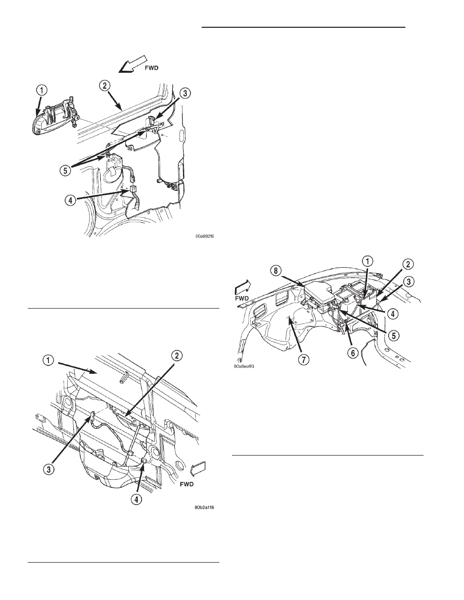
Fig. 2 Door Lock Cylinder Switch Remove/Install -
Typical
1 – DOOR OUTSIDE LATCH HANDLE
2 – DOOR
3 – DOOR LOCK CYLINDER SWITCH
4 – CONNECTOR
5 – RETAINERS
Fig. 3 Liftgate Lock Cylinder Switch Remove/Install
1 – LIFTGATE INNER PANEL
2 – LIFTGATE LATCH OUTSIDE HANDLE
3 – LIFTGATE LOCK CYLINDER SWITCH
4 – WIRE HARNESS CONNECTOR
Fig. 4 Power Distribution Center
1 – CLIP
2 – BATTERY
3 – TRAY
4 – NEGATIVE CABLE
5 – POSITIVE CABLE
6 – CLIP
7 – FENDER INNER SHIELD
8 – POWER DISTRIBUTION CENTER
8Q - 6
VEHICLE THEFT/SECURITY SYSTEMS
DN
REMOVAL AND INSTALLATION (Continued)