Dodge Durango (DN). Manual - part 307
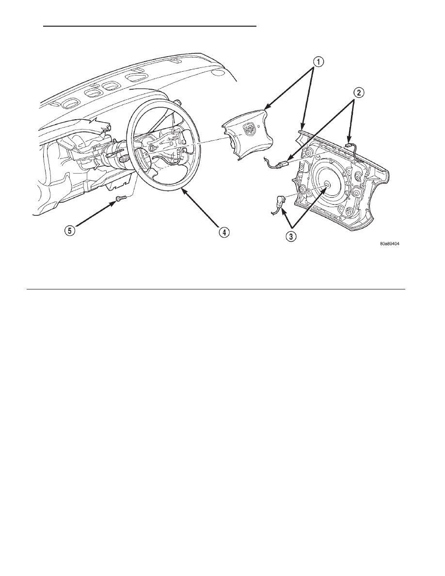
INSTALLATION
WARNING:
•
USE EXTREME CARE TO PREVENT ANY FOR-
EIGN MATERIAL FROM ENTERING THE DRIVER
SIDE
AIRBAG
MODULE,
OR
BECOMING
ENTRAPPED BETWEEN THE AIRBAG CUSHION
AND THE DRIVER SIDE AIRBAG TRIM COVER.
FAILURE TO OBSERVE THIS WARNING COULD
RESULT IN OCCUPANT INJURIES UPON AIRBAG
DEPLOYMENT.
•
THE DRIVER SIDE AIRBAG MODULE TRIM
COVER MUST NEVER BE PAINTED. REPLACEMENT
TRIM COVERS ARE SERVICED IN THE ORIGINAL
COLORS. PAINT MAY CHANGE THE WAY IN WHICH
THE MATERIAL OF THE TRIM COVER RESPONDS
TO
AN
AIRBAG
DEPLOYMENT.
FAILURE
TO
OBSERVE
THIS
WARNING
COULD
RESULT
IN
OCCUPANT
INJURIES
UPON AIRBAG
DEPLOY-
MENT.
(1) When installing the driver side airbag module,
reconnect the clockspring airbag wire harness con-
nector to the airbag module connector receptacle by
pressing straight in on the connector. You can be cer-
tain that the connector is fully engaged by listening
carefully for a distinct audible click as the connector
snaps into place.
(2) Reconnect the clockspring horn switch wire
harness connector to the horn switch feed wire con-
nector, which is located on the back of the airbag
module.
(3) Carefully position the driver side airbag mod-
ule in the steering wheel. Be certain that the clock-
spring wire harnesses in the steering wheel hub area
are not pinched between the airbag module and the
steering wheel.
(4) From the underside of the steering wheel,
install and tighten the two driver side airbag module
mounting screws. Tighten the screws to 10.2 N·m (90
in. lbs.).
(5) Do not reconnect the battery negative cable at
this time. Refer to Airbag System in the Diagnosis
and Testing section of this group for the proper pro-
cedures.
DRIVER SIDE AIRBAG MODULE TRIM COVER
The horn switch is integral to the driver side air-
bag module trim cover. If either component is faulty
or damaged, the entire driver side airbag module
trim cover and horn switch unit must be replaced.
Fig. 4 Driver Side Airbag Module Remove/Install
1 – AIRBAG MODULE
2 – HORN SWITCH CONNECTOR
3 – AIRBAG CONNECTOR
4 – STEERING WHEEL
5 – SCREW
DN
PASSIVE RESTRAINT SYSTEMS
8M - 7
REMOVAL AND INSTALLATION (Continued)