Dodge Durango (DN). Manual - part 295
wire harness connector to the multi-function switch
connector receptacle.
(8) Disconnect the instrument panel wire harness
connector from the multi-function switch connector
receptacle.
(9) Remove the multi-function switch from the
steering column.
INSTALLATION
(1) Position the multi-function switch onto the
steering column.
(2) Reconnect the instrument panel wire harness
connector to the multi-function switch connector
receptacle.
(3) Install and tighten the screw that secures the
instrument panel wire harness connector to the
multi-function switch connector receptacle. Tighten
the screw to 2 N·m (17 in. lbs.).
(4) Install and tighten the two screws that secure
the multi-function switch to the steering column.
Tighten the screws to 2 N·m (17 in. lbs.).
(5) Install the lower fixed column shroud onto the
steering column.
(6) Install both the upper and lower shrouds onto
the steering column.
(7) If the vehicle is so equipped, install the tilt
steering column lever onto the left side of the steer-
ing column by screwing it into place.
(8) Reconnect the battery negative cable.
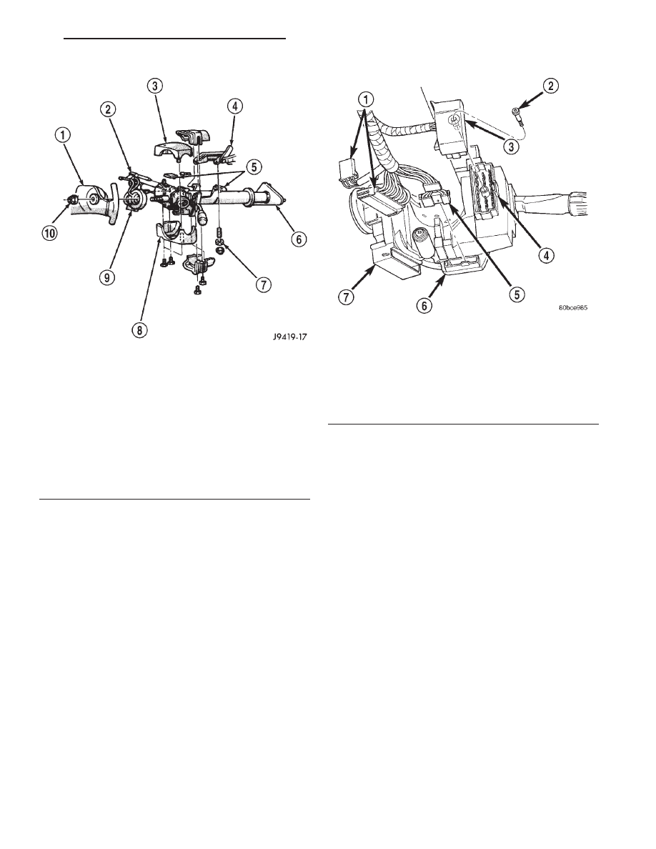
Fig. 5 Steering Column Shrouds Remove/Install -
Typical
1 – STEERING WHEEL
2 – TILT LEVER
3 – UPPER SHROUD
4 – PANEL BRACKET
5 – SPACER
6 – TOE PLATE
7 – NUT
8 – LOWER SHROUD
9 – CLOCK SPRING
10 – NUT
Fig. 6 Multi-Function Switch Connector
1 – WIRE HARNESS CONNECTORS
2 – SCREW
3 – WIRE HARNESS CONNECTOR
4 – MULTI-FUNCTION SWITCH
5 – WIRE HARNESS CONNECTOR
6 – CLOCKSPRING
7 – IGNITION SWITCH
DN
TURN SIGNAL AND HAZARD WARNING SYSTEMS
8J - 7
REMOVAL AND INSTALLATION (Continued)