Dodge Durango (DN). Manual - part 283
CENTRAL TIMER MODULE
Before replacing a high-line Central Timer Module
(CTM), use a DRB scan tool to determine the current
settings for the CTM programmable features. These
settings should be duplicated in the replacement
CTM using the DRB scan tool, before returning the
vehicle to service.
WARNING: ON VEHICLES EQUIPPED WITH AIR-
BAGS,
REFER
TO
GROUP
8M
-
PASSIVE
RESTRAINT SYSTEMS BEFORE ATTEMPTING ANY
STEERING
WHEEL,
STEERING
COLUMN,
OR
INSTRUMENT PANEL COMPONENT DIAGNOSIS OR
SERVICE. FAILURE TO TAKE THE PROPER PRE-
CAUTIONS COULD RESULT IN ACCIDENTAL AIR-
BAG DEPLOYMENT AND POSSIBLE PERSONAL
INJURY.
REMOVAL
(1) Disconnect and isolate the battery negative
cable.
(2) Remove the glove box from the instrument
panel. Refer to Glove Box - Removal in the
Removal and Installation section of this group for the
procedures.
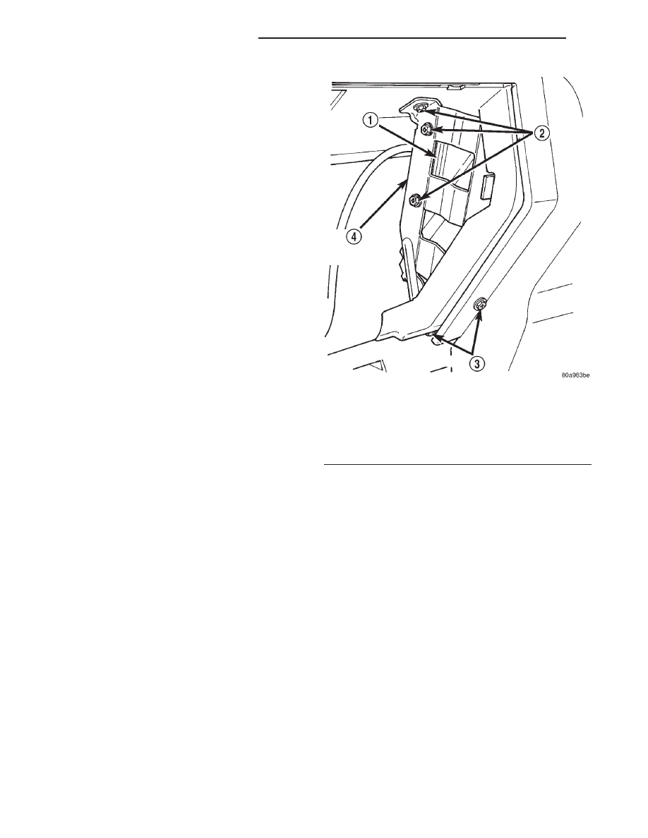
(3) Remove the three screws that secure the
bracket on the outboard side of the glove box opening
to the instrument panel (Fig. 22).
(4) Remove the two screws that secure the Central
Timer Module (CTM) mounting bracket to the
bracket on the outboard side of instrument panel
glove box opening (Fig. 23).
(5) Remove the bracket on the outboard side of the
glove box opening from the instrument panel through
the glove box opening.
(6) Move the CTM and its mounting bracket into
the glove box opening far enough to access and dis-
engage the instrument panel wire harness retainer
from the CTM mounting bracket.
(7) Disconnect the instrument panel wire harness
connector(s) (one connector for the base CTM, two
connectors for high-line CTM) from the CTM connec-
tor receptacle(s).
(8) Remove the CTM and mounting bracket unit
from the instrument panel through the glove box
opening.
INSTALLATION
(1) Position the CTM and mounting bracket unit
in the instrument panel glove box opening.
(2) Reconnect the instrument panel wire harness
connector(s) (one connector for the base CTM, two
connectors for high-line CTM) to the CTM connector
receptacle(s).
(3) Engage the instrument panel wire harness
retainer with the hole in the CTM mounting bracket.
(4) Engage the tab on the outboard end of the
CTM mounting bracket in the slot in the right
instrument panel end bracket.
(5) Working through the instrument panel glove
box opening, position the outboard glove box opening
bracket to the CTM mounting bracket.
(6) Install and tighten the two screws that secure
the Central Timer Module (CTM) mounting bracket
to the bracket on the outboard side of instrument
panel glove box opening. Tighten the screws to 2.2
N·m (20 in. lbs.).
(7) Install and tighten the three screws that secure
the bracket on the outboard side of the glove box
opening to the instrument panel. Tighten the screws
to 2.2 N·m (20 in. lbs.).
(8) Install the glove box onto the instrument panel.
Refer to Glove Box - Installation in the Removal
and Installation section of this group for the proce-
dures.
(9) Reconnect the battery negative cable.
Fig. 22 Outboard Glove Box Opening Bracket
Remove/Install
1 – CTM BRACKET
2 – SCREWS
3 – SCREWS
4 – GLOVE BOX OPENING BRACKET
8E - 26
INSTRUMENT PANEL SYSTEMS
DN
REMOVAL AND INSTALLATION (Continued)