Dodge Durango (DN). Manual - part 276
shifter must be in PARK position. The park lock
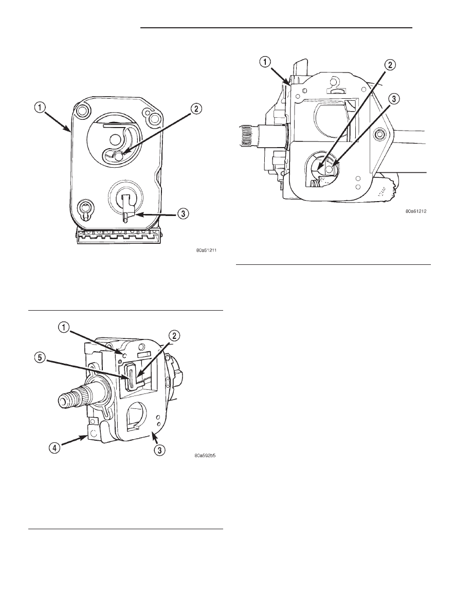
dowel pin on rear of ignition switch (Fig. 41) must
also be properly indexed into the park lock linkage
(Fig. 42) before installing switch.
(6) The flag at rear of ignition switch (Fig. 41)
must be properly indexed into steering column before
installing switch. This flag is used to operate the
steering wheel lock lever in steering column (Fig. 43).
This lever allows steering wheel position to be locked
when key switch is in LOCK position.
(7) Place ignition switch in LOCK position. The
switch is in the LOCK position when column lock
flag is parallel to ignition switch terminals (Fig. 41).
(8) Automatic Transmission Only: Apply a light
coating of grease to park lock dowel pin and park
lock slider linkage. Before installing switch, push the
park lock slider linkage (Fig. 42) forward until it bot-
toms. Do a final positioning by pulling it rearward
about one-quarter inch.
(9) Apply a light coating of grease to both column
lock flag and shaft at end of flag.
(10) Place ignition switch into openings on steering
column.
(a) Automatic Transmission Only: Be sure park
lock dowel pin on rear of ignition switch enters slot
in park lock slider linkage (Fig. 42).
(b) Be sure flag on rear of switch is positioned
above steering wheel lock lever (Fig. 43).
(c) Align dowel pins on rear of switch into holes
on side of steering column.
(d) Install 3 ignition switch mounting screws.
Tighten screws to 2 N·m
6.5 N·m (17 in. lbs. 6 5
in. lbs.) torque.
(e) After installing ignition switch, rotate igni-
tion key from LOCK to ON position. Verify that
park lock slider moves in slider slot, allowing gear-
shift lever to be moved out of PARK (auto. trans.
only). If slider does not move, and gearshift lever is
locked in PARK, the ignition switch park lock
dowel pin, on rear of ignition switch, is not prop-
Fig. 41 Ignition Switch View From Column
1 – REAR OF IGNITION SWITCH
2 – PARK LOCK DOWEL PIN
(LOCK POSITION)
3 – FLAG
(LOCK POSITION)
Fig. 42 Park Lock Linkage—Automatic
Transmission—Typical
1 – DOWEL LOCATING HOLES (2)
2 – PARK LOCK SLIDER LINKAGE
3 – IGNITION SWITCH MOUNTING PAD
4 – STEERING COLUMN
5 – SLOT
Fig. 43 Steering Wheel Lock Lever
1 – STEERING COLUMN
2 – STEERING WHEEL LOCK LEVER
3 – LOCATOR
(SHAFT AT END OF FLAG)
8D - 20
IGNITION SYSTEM
DN
REMOVAL AND INSTALLATION (Continued)