Dodge Durango (DN). Manual - part 234
(13) Lubricate and install thrust washers behind
pinion gears and align washers with a small screw
driver. Insert mate shaft into each pinion gear to ver-
ify alignment.
(14) Remove Forcing Screw 6960-4, Step Plate
8140–2, and Threaded Adapter 8140-1.
(15) Install pinion gear mate shaft and align holes
in shaft and case.
(16) Install the pinion mate shaft lock screw finger
tight to hold shaft during differential installation.
(17) Lubricate all differential components with
hypoid gear lubricant.
9 1/4 TRAC-LOK
Y DIFFERENTIAL
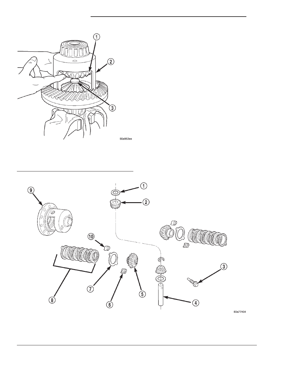
The Trac–lok
y differential components are illus-
trated in (Fig. 56). Refer to this illustration during
repair service.
DISASSEMBLY
(1) Clamp Side Gear Holding Tool 8136 in a vise.
(2) Position the differential case on Side Gear
Holding Tool 8136 (Fig. 57).
(3) Remove ring gear, if necessary. Ring gear
removal is necessary only if the ring gear is to be
replaced. The Trac-lok
y differential can be serviced
with the ring gear installed.
Fig. 56 Trac–lok
Y
Differential Components
1 – THRUST WASHER
2 – PINION
3 – SHAFT LOCK SCREW
4 – PINION MATE SHAFT
5 – SIDE GEAR
6 – RETAINER
7 – DISC
8 – CLUTCH PACK
9 – DIFFERENTIAL CASE
10 – RETAINER
Fig. 55 Upper Side Gear & Clutch Disc Pack
Installation
1 – UPPER SIDE GEAR AND CLUTCH DISC PACK
2 – DIFFERENTIAL CASE
3 – SPECIAL TOOL 8140–2
3 - 86
8 1/4 AND 9 1/4 AXLE
DN
DISASSEMBLY AND ASSEMBLY (Continued)