Dodge Durango (DN). Manual - part 219
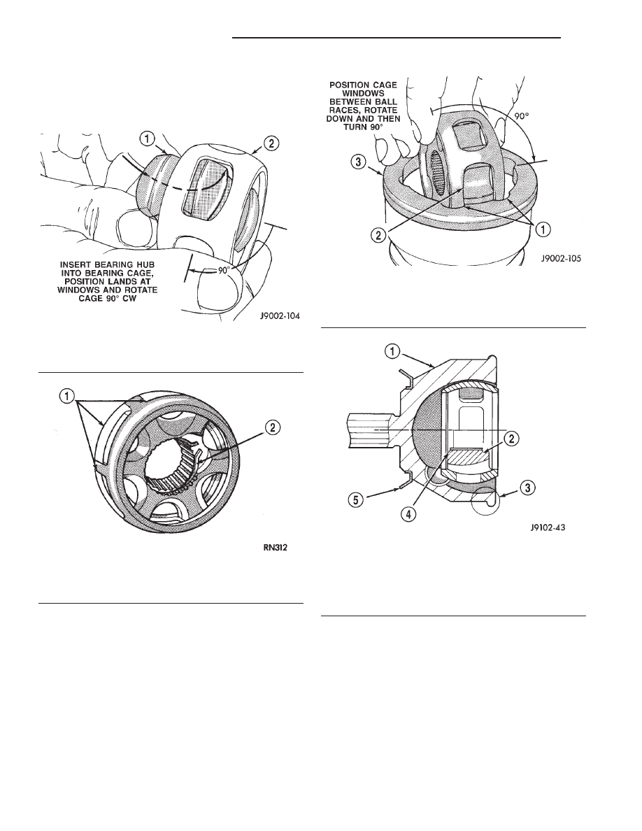
(3) Insert one of the bearing hub lands into a bear-
ing cage window (Fig. 18). Roll the hub into the cage
(Fig. 19). Rotate the bearing hub 90° to complete the
installation (Fig. 20).
(4) Insert bearing cage/hub into the housing (Fig.
21). Rotate the cage/hub 90° to complete the installa-
tion (Fig. 22).
(5) Apply the lubricant included with the replace-
ment boot to the ball raceways. Spread the lubricant
equally between all the raceways. One packet of
lubricant is sufficient to lubricate the complete C/V
joint.
(6) Tilt the bearing hub and cage and install the
balls in the raceways (Fig. 23).
(7) Apply a small amount of lubricant to inner
diameter of slinger. Place slinger squarely on the
outer C/V joint. Use installer tool L-4518-1 from tool
set L-4518 and hammer slinger onto joint until it
seats (Fig. 24).
CAUTION: Prevent damage to the slinger after
installation or a when a replacement outer C/V joint
is installed.
Fig. 19 Bearing Hub Installation
1 – BEARING HUB
2 – BEARING CAGE
Fig. 20 Assembled Bearing Cage & Hub
1 – CAGE WINDOWS
2 – CIRCLIP RETAINER
Fig. 21 Bearing Cage & Hub Installation
1 – BALL RACE
2 – BEARING CAGE WINDOW
3 – CV JOINT HOUSING (OUTER)
Fig. 22 Bearing Cage & Hub Installed In Housing
1 – CV JOINT HOUSING (OUTER)
2 – BEARING HUB
LARGE COUNTERBORE OUTWARD
3 – BOOT RETAINING SHOULDER
4 – BEARING HUB
SMALL COUNTERBORE INWARD
5 – SLINGER
3 - 26
FRONT AXLE DRIVESHAFTS
DN
DISASSEMBLY AND ASSEMBLY (Continued)