Dodge Durango (DN). Manual - part 203
three places. Tighten the mounting screws to 2.2 N·m
(20 in. lbs.).
(2) Remove the tape or plugs from the refrigerant
line fittings at the rear of the underbody liquid and
suction lines and at the B-pillar liquid and suction
lines. Connect the underbody refrigerant lines to the
B-pillar refrigerant lines. See Refrigerant Line Cou-
pler in the Removal and Installation section of this
group for the procedures.
(3) Lower the vehicle.
(4) From the engine compartment, remove the tape
or plugs from the refrigerant line fittings at the front
of the underbody liquid and suction lines and at the
liquid line extension and the suction line jumper.
Connect the underbody refrigerant lines to the
engine compartment refrigerant lines. See Refriger-
ant Line Coupler in the Removal and Installation
section of this group for the procedures.
(5) Connect the battery negative cable.
(6) Evacuate the refrigerant system. See Refriger-
ant System Evacuate in the Service Procedures sec-
tion of this group.
(7) Charge the refrigerant system. See Refrigerant
System Charge in the Service Procedures section of
this group.
VACUUM CHECK VALVE
(1) Unplug the vacuum supply line connector at
the vacuum check valve (Fig. 88).
(2) Note the orientation of the check valve in the
vacuum supply line for correct reinstallation.
(3) Unplug the vacuum check valve from the vac-
uum supply line fittings.
(4) Reverse the removal procedures to install.
VACUUM RESERVOIR
(1) Disconnect and isolate the battery negative
cable.
(2) Remove the wiper arms from the wiper pivots.
Refer to Wiper Arm in the Removal and Installation
section of Group 8K - Wiper and Washer Systems for
the procedures.
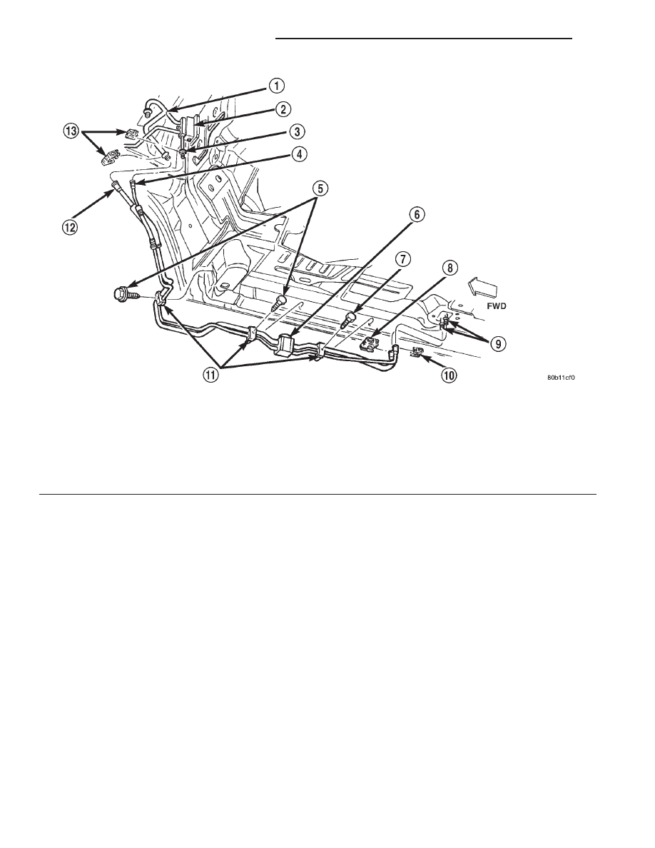
Fig. 87 Underbody Refrigerant Line Remove/Install
1 – SUCTION LINE JUMPER
2 – FRONT EXPANSION VALVE
3 – LIQUID LINE EXTENSION
4 – UNDERBODY LIQUID LINE
5 – SCREWS
6 – REAR EXPANSION VALVE
7 – SCREW
8 – CLIP
9 – B-PILLAR REFRIGERANT LINES
10 – CLIP
11 – CLAMPS
12 – UNDERBODY SUCTION LINE
13 – CLIPS
24 - 70
HEATING AND AIR CONDITIONING
DN
REMOVAL AND INSTALLATION (Continued)