Dodge Durango (DN). Manual - part 159
 

  Index      Dodge     Dodge Durango (DN) - service repair manual 2000 year


Search            


Content   ..  157  158  159  160   ..


Dodge Durango (DN). Manual - part 159


INSTALLATION

(1) Transfer applicable components.
(2) Install outboard seats.
(3) Install 2nd row seat assembly.

2ND ROW CENTER SEAT BACK

REMOVAL

(1) Tumble outboard seats forward.
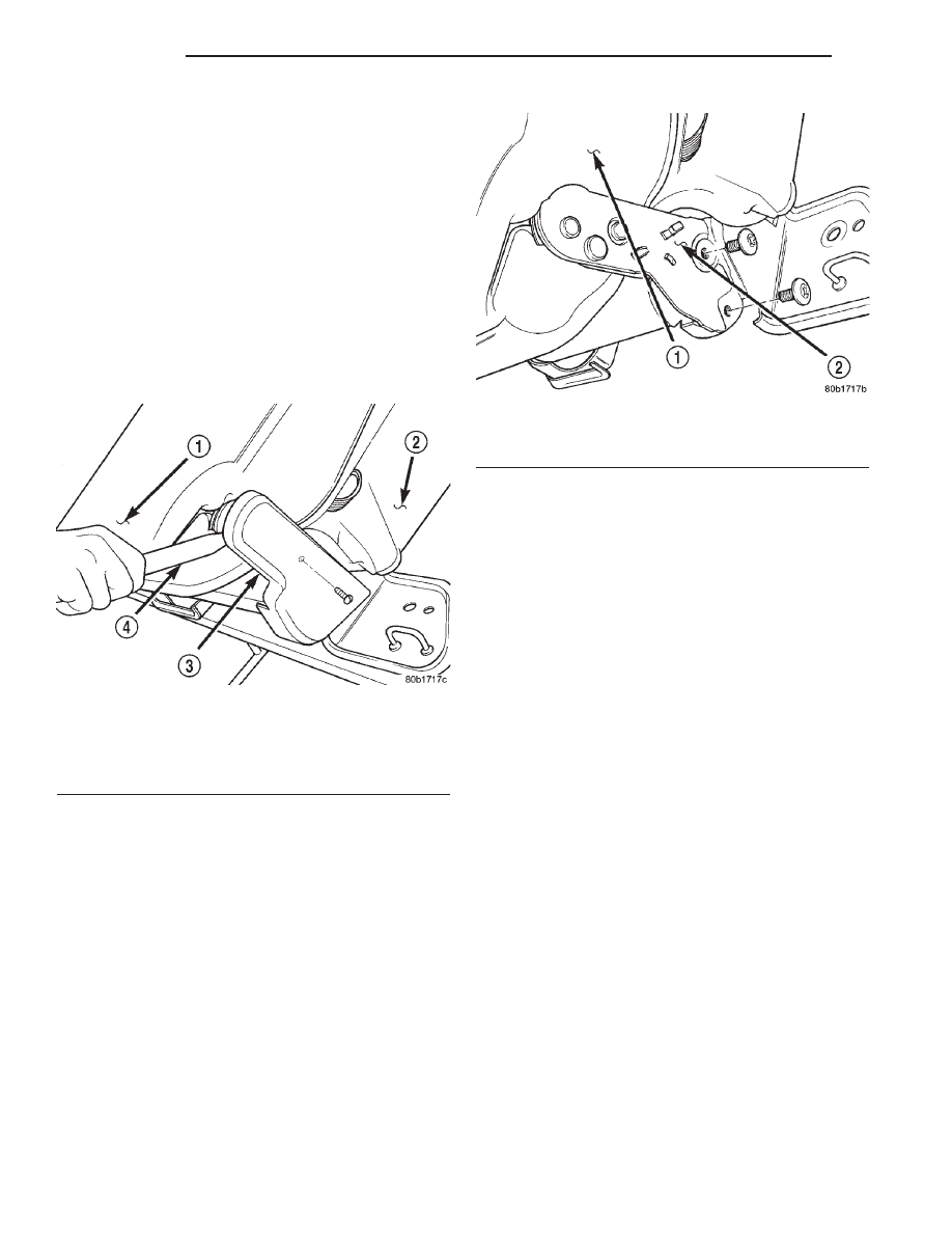
(2) Remove screw attaching cover to hinge.
(3) Using a trim stick, pry trim covers from center

seat back to center seat cushion hinge (Fig. 13).

(4) Remove bolts attaching center seat back to seat

cushion (Fig. 14).

(5) Separate center seat back from seat cushion.

INSTALLATION

(1) Position center seat back on seat cushion.
(2) Install bolts attaching center seat back to seat

cushion (Fig. 14). Tighten bolt located in round hole
first than bolt located in slotted hole. Tighten bolts to
27 N·m (19 ft. lbs.) torque.

(3) Install covers on center seat back to seat cush-

ion hinge.

(4) Install screw attaching cover to hinge.
(5) Return outboard seats to seating position.

2ND ROW CENTER SEAT BACK COVER

REMOVAL

(1) Remove center seat back.
(2) Disengage J-straps on bottom.
(3) Remove hook and loop fasteners on left and

right side.

(4) Remove the cup holder.
(5) Roll cover off seat back.

INSTALLATION

(1) Position cover on seat back.
(2) Engage J-straps.
(3) Install center seat back.
(4) Engage hook and loop fasteners.
(5) Install the cup holder.

3RD ROW SEAT CUSHION COVER

NOTE: The cushion cover is bonded to the seat
foam cushion.

REMOVAL

(1) Lift and rotate seat cushion forward.
(2) Disengage J-straps on underside of seat.
(3) Disengage J-straps on each side of seat.
(4) Separate cover/cushion from seat frame.

INSTALLATION

(1) Position cover/cushion on seat frame.
(2) Engage J-straps on each side of seat.
(3) Engage J-straps on underside of seat.
(4) Return seat to seating position.

3RD ROW SEAT CUSHION FRAME

REMOVAL

(1) Lift seat cushion upward.
(2) From the underside of the seat cushion, remove

bolts attaching the seat cushion/frame to lift bar.

(3) Separate seat cushion/frame from vehicle.

Fig. 13 2nd Row Center Seat Back Hinge Cover

1 – 2ND ROW CENTER SEAT BACK
2 – SEAT CUSHION
3 – HINGE COVER
4 – TRIM STICK

Fig. 14 2nd Row Center Seat Back

1 – 2ND ROW CENTER SEAT BACK
2 – HINGE

23 - 16

BODY

DN

REMOVAL AND INSTALLATION (Continued)

INSTALLATION

(1) Position seat cushion/frame in vehicle.
(2) Install the bolts attaching seat cushion/frame

to lift bar. Tighten bolts to 24 N·m (17 ft. lbs.) torque.

(3) Place seat cushion in seating position.

HEAD RESTRAINT SLEEVE

NOTE: When removing the head restraint sleeves
and guides, the retaining tabs on the sleeves will be
damaged during the removal process. Check the
availability of replacement parts before servicing.

REMOVAL

(1) Remove head restraint.
(2) Using a trim stick, pry head restraint sleeves

and guides from seat back. (Fig. 15).

(3) Separate head restraint sleeves and guides

from seat back and discard.

INSTALLATION

(1) Position new head restraint sleeves and guides

in seat back

(2) Rotate head restraint sleeve until aligned with

slot in the guide and press downward to secure.
Ensure head restraint sleeve is anchored securely.

(3) Install head restraint.

3RD ROW SEAT BACK

REMOVAL

(1) Lift seat cushion upward and move into cargo

floor position.

(2) Remove pivot bolts attaching seat back to

mounting brackets.

(3) Separate seat back.

INSTALLATION

(1) Position seat back in vehicle.
(2) Install pivot bolts attaching seat back to mounting

brackets. Tighten bolts to 24 N·m (17 ft. lbs.) torque.

3RD ROW SEAT BACK COVER

NOTE: THE CLOTH TRIM IS BONDED TO THE
BACK FOAM.

REMOVAL

(1) Remove 3rd row seat back.
(2) Remove head restraints, and head restraint

sleeves and guides. Discard sleeves and guides.

(3) Disengage J-straps on each side of seat back

(Fig. 16).

(4) Disengage J-strap at base of seat back.
(5) Lift the back of the cover upward and slide

seat back frame out of cover.

INSTALLATION

(1) Slide seat back frame into cover.
(2) Engage J-straps on each side of seat back.
(3) Engage J-strap at base of seat back.
(4) Install new head restraint sleeves and guides.

Install head restraints.

(5) Install 3rd row seat back.

Fig. 15 Head Restrain Sleeve

1 – HEAD RESTRAINT SLEEVE
2 – SEAT BACK
3 – TRIM STICK

Fig. 16 3rd Row Seat Back Cover J-Strap

1 – 3RD ROW SEAT BACK
2 – J-STRAP

DN

BODY

23 - 17

REMOVAL AND INSTALLATION (Continued)

BODY COMPONENT SERVICE

TABLE OF CONTENTS

page

page

DESCRIPTION AND OPERATION

BODY COMPONENTS . . . . . . . . . . . . . . . . . . . . . 19
INTERIOR TRIM PANELS. . . . . . . . . . . . . . . . . . . 19

DIAGNOSIS AND TESTING

WATER LEAKS . . . . . . . . . . . . . . . . . . . . . . . . . . 19

SERVICE PROCEDURES

BODY LUBRICATION . . . . . . . . . . . . . . . . . . . . . . 20
HEAT STAKING . . . . . . . . . . . . . . . . . . . . . . . . . . 20

REMOVAL AND INSTALLATION

GRILLE . . . . . . . . . . . . . . . . . . . . . . . . . . . . . . . . 21
HOOD . . . . . . . . . . . . . . . . . . . . . . . . . . . . . . . . . 21
HOOD SILENCER PAD . . . . . . . . . . . . . . . . . . . . 22
HOOD HINGE . . . . . . . . . . . . . . . . . . . . . . . . . . . 22
HOOD SAFETY LATCH . . . . . . . . . . . . . . . . . . . . 22
HOOD LATCH STRIKER. . . . . . . . . . . . . . . . . . . . 22
HOOD LATCH . . . . . . . . . . . . . . . . . . . . . . . . . . . 23
HOOD RELEASE CABLE . . . . . . . . . . . . . . . . . . . 23
COWL GRILLE . . . . . . . . . . . . . . . . . . . . . . . . . . . 24
COWL SEAL . . . . . . . . . . . . . . . . . . . . . . . . . . . . 24
HOOD SEAL . . . . . . . . . . . . . . . . . . . . . . . . . . . . 25
FRONT WHEELHOUSE LINER. . . . . . . . . . . . . . . 25
LEFT FRONT FENDER. . . . . . . . . . . . . . . . . . . . . 26
RIGHT FRONT FENDER . . . . . . . . . . . . . . . . . . . 26
RUNNING BOARD . . . . . . . . . . . . . . . . . . . . . . . . 28
EXTERIOR NAMEPLATES . . . . . . . . . . . . . . . . . . 28
DECALS. . . . . . . . . . . . . . . . . . . . . . . . . . . . . . . . 30
SIDE VIEW MIRROR . . . . . . . . . . . . . . . . . . . . . . 30
FRONT DOOR TRIM PANEL . . . . . . . . . . . . . . . . 31
FRONT DOOR WATERDAM . . . . . . . . . . . . . . . . . 31
FRONT DOOR . . . . . . . . . . . . . . . . . . . . . . . . . . . 32
FRONT DOOR HINGE . . . . . . . . . . . . . . . . . . . . . 33
FRONT DOOR OUTSIDE HANDLE . . . . . . . . . . . . 33
FRONT DOOR LOCK CYLINDER . . . . . . . . . . . . . 33
LOCK CYLINDERS. . . . . . . . . . . . . . . . . . . . . . . . 35
FRONT DOOR LATCH . . . . . . . . . . . . . . . . . . . . . 35
FRONT DOOR LATCH STRIKER . . . . . . . . . . . . . 35
FRONT DOOR INSIDE HANDLE ACTUATOR . . . . 35
FRONT DOOR INNER BELT WEATHERSTRIP . . . 36
FRONT DOOR OUTER BELT WEATHERSTRIP . . 36
FRONT DOOR GLASS . . . . . . . . . . . . . . . . . . . . . 36
FRONT DOOR WINDOW REGULATOR . . . . . . . . 37
FRONT DOOR LOWER GLASS RUN

CHANNELS. . . . . . . . . . . . . . . . . . . . . . . . . . . . 37

FRONT DOOR GLASS RUN WEATHERSTRIP . . . 38
FRONT DOOR OPENING WEATHERSTRIP . . . . . 38
FRONT DOOR SECONDARY SEAL . . . . . . . . . . . 38
REAR DOOR TRIM PANEL. . . . . . . . . . . . . . . . . . 38
REAR DOOR WATERDAM . . . . . . . . . . . . . . . . . . 40
REAR DOOR . . . . . . . . . . . . . . . . . . . . . . . . . . . . 40

REAR DOOR HINGE . . . . . . . . . . . . . . . . . . . . . . 40
REAR DOOR OUTSIDE HANDLE . . . . . . . . . . . . . 40
REAR DOOR LATCH . . . . . . . . . . . . . . . . . . . . . . 41
REAR DOOR LATCH STRIKER . . . . . . . . . . . . . . 41
REAR DOOR INSIDE HANDLE ACTUATOR . . . . . 42
REAR DOOR INNER BELT WEATHERSTRIP . . . . 42
REAR DOOR OUTER BELT WEATHERSTRIP . . . 42
REAR DOOR OPENING WEATHERSTRIP . . . . . . 42
REAR DOOR WINDOW REGULATOR . . . . . . . . . 42
REAR DOOR GLASS RUN WEATHERSTRIP . . . . 43
REAR DOOR GLASS RUN CHANNELS . . . . . . . . 44
REAR DOOR GLASS . . . . . . . . . . . . . . . . . . . . . . 44
C—PILLAR SEAL . . . . . . . . . . . . . . . . . . . . . . . . . 44
REAR DOOR SECONDARY SEAL . . . . . . . . . . . . 45
ROOF RAIL WEATHERSTRIP AND RETAINER . . . 45
BODY SIDE MOLDINGS. . . . . . . . . . . . . . . . . . . . 45
WHEEL OPENING MOLDING . . . . . . . . . . . . . . . . 46
FUEL FILLER DOOR . . . . . . . . . . . . . . . . . . . . . . 47
REAR WHEEL HOUSE LINER . . . . . . . . . . . . . . . 47
LIFTGATE TRIM PANEL . . . . . . . . . . . . . . . . . . . . 47
LIFTGATE HINGE. . . . . . . . . . . . . . . . . . . . . . . . . 48
LIFTGATE SUPPORT CYLINDER . . . . . . . . . . . . . 48
LIFTGATE . . . . . . . . . . . . . . . . . . . . . . . . . . . . . . 49
LIFTGATE OUTSIDE HANDLE . . . . . . . . . . . . . . . 49
LIFTGATE LOCK CYLINDER . . . . . . . . . . . . . . . . 49
LIFTGATE LATCH . . . . . . . . . . . . . . . . . . . . . . . . 50
LIFTGATE LATCH STRIKER . . . . . . . . . . . . . . . . . 50
LIFTGATE OPENING WEATHERSTRIP . . . . . . . . 50
LIFTGATE MOLDING . . . . . . . . . . . . . . . . . . . . . . 51
LUGGAGE RACK . . . . . . . . . . . . . . . . . . . . . . . . . 51
COWL TRIM COVER . . . . . . . . . . . . . . . . . . . . . . 52
A-PILLAR GRAB HANDLE . . . . . . . . . . . . . . . . . . 52
A-PILLAR TRIM . . . . . . . . . . . . . . . . . . . . . . . . . . 52
DOOR SILL TRIM . . . . . . . . . . . . . . . . . . . . . . . . . 52
B-PILLAR TRIM . . . . . . . . . . . . . . . . . . . . . . . . . . 53
C-PILLAR TRIM . . . . . . . . . . . . . . . . . . . . . . . . . . 53
LIFTGATE OPENING UPPER TRIM . . . . . . . . . . . 53
D-PILLAR TRIM . . . . . . . . . . . . . . . . . . . . . . . . . . 54
QUARTER PANEL TRIM . . . . . . . . . . . . . . . . . . . . 55
LIFTGATE SCUFF PLATE. . . . . . . . . . . . . . . . . . . 56
FRONT SEAT BELT RETRACTOR . . . . . . . . . . . . 56
FRONT SEAT BELT BUCKLE . . . . . . . . . . . . . . . . 57
2ND ROW SEAT BELT RETRACTOR . . . . . . . . . . 57
2ND ROW SEAT BELT BUCKLE . . . . . . . . . . . . . . 57
3RD ROW SEAT BELT RETRACTOR . . . . . . . . . . 57
3RD ROW SEAT BELT BUCKLE . . . . . . . . . . . . . . 59
BUCKET SEAT . . . . . . . . . . . . . . . . . . . . . . . . . . . 59
2ND ROW SEAT . . . . . . . . . . . . . . . . . . . . . . . . . 61
3RD ROW SEAT . . . . . . . . . . . . . . . . . . . . . . . . . 61

23 - 18

BODY

DN

FLOOR CONSOLE . . . . . . . . . . . . . . . . . . . . . . . . 62
FLOOR CARPET . . . . . . . . . . . . . . . . . . . . . . . . . 63
FLOOR CARGO STORAGE DOOR. . . . . . . . . . . . 64
REARVIEW MIRROR . . . . . . . . . . . . . . . . . . . . . . 64
REARVIEW MIRROR SUPPORT BRACKET . . . . . 64
SUNVISOR. . . . . . . . . . . . . . . . . . . . . . . . . . . . . . 64
COAT HOOK . . . . . . . . . . . . . . . . . . . . . . . . . . . . 65
OVERHEAD ASSIST HANDLE . . . . . . . . . . . . . . . 65
HEADLINER . . . . . . . . . . . . . . . . . . . . . . . . . . . . . 66

ADJUSTMENTS

HOOD . . . . . . . . . . . . . . . . . . . . . . . . . . . . . . . . . 66
HOOD LATCH STRIKER. . . . . . . . . . . . . . . . . . . . 67
HOOD LATCH . . . . . . . . . . . . . . . . . . . . . . . . . . . 67

DOOR . . . . . . . . . . . . . . . . . . . . . . . . . . . . . . . . . 67
DOOR LATCH ADJUSTMENT . . . . . . . . . . . . . . . . 67
LIFTGATE . . . . . . . . . . . . . . . . . . . . . . . . . . . . . . 67

SPECIFICATIONS

WELD LOCATIONS . . . . . . . . . . . . . . . . . . . . . . . 68
STRUCTURAL ADHESIVE LOCATIONS . . . . . . . 100
BODY SEALING LOCATIONS . . . . . . . . . . . . . . . 101
BODY GAP AND FLUSH MEASUREMENTS . . . . 117
BODY OPENING DIMENSIONS . . . . . . . . . . . . . 119
TORQUE SPECIFICATIONS . . . . . . . . . . . . . . . . 122

SPECIAL TOOLS

BODY. . . . . . . . . . . . . . . . . . . . . . . . . . . . . . . . . 122

DESCRIPTION AND OPERATION

BODY COMPONENTS

DESCRIPTION

Exterior sheet metal components make up the

exterior of the vehicle. Some exterior metal systems
are welded assemblies, such as doors and hoods.
Some exterior trim items are made of composite.

OPERATION

The exterior is finished in various metal stampings

and composite moldings. These assemblies give the
vehicle a finished appearance and protect the occu-
pants from the elements. Some components are part
of the energy absorbing system used to protect the
occupants in collisions. The exterior sheet metal is
repairable and adjustable for fit and finish. Welded
and bonded component systems are adjustable as a
system. Trim components made of composite are
stamped with the type of material used. Daimler-
Chrysler uses various fasteners to retain trim items.
At times, it is not possible to remove trim items
without damaging the fastener. If it is not possible to
remove an item without damaging a component, cut
or break the fasteners and use new ones when
installing the component.

INTERIOR TRIM PANELS

CAUTION: Do not attempt to remove interior trim
panels/moldings without first removing the neces-
sary adjacent panels.

To avoid damaging the panels, ensure that all the

screws and clips are removed before attempting to
remove an interior trim panel/molding. Trim panels
are somewhat flexible but can be damaged if
handled improperly.

DIAGNOSIS AND TESTING

WATER LEAKS

Water leaks can be caused by poor sealing,

improper body component alignment, body seam
porosity, missing plugs, or blocked drain holes. Cen-
trifugal and gravitational force can cause water to
drip from a location away from the actual leak point,
making leak detection difficult. All body sealing
points should be water tight in normal wet-driving
conditions. Water flowing downward from the front of
the vehicle should not enter the passenger or luggage
compartment.

Moving

sealing

surfaces

will

not

always seal water tight under all conditions. At
times, side glass or door seals will allow water to
enter the passenger compartment during high pres-
sure washing or hard driving rain (severe) condi-
tions.

Overcompensating

on

door

or

glass

adjustments to stop a water leak that occurs under
severe conditions can cause premature seal wear and
excessive closing or latching effort. After completing
a repair, water test vehicle to verify leak has stopped
before returning vehicle to use.

VISUAL INSPECTION BEFORE WATER LEAK TESTS

Verify that floor and body plugs are in place, body

drains are clear, and body components are properly
aligned and sealed. If component alignment or seal-
ing is necessary, refer to the appropriate section of
this group for proper procedures.

WATER LEAK TESTS

WARNING: DO NOT USE ELECTRIC SHOP LIGHTS
OR TOOLS IN WATER TEST AREA. PERSONAL
INJURY CAN RESULT.

When the conditions causing a water leak have

been determined, simulate the conditions as closely
as possible.

DN

BODY

23 - 19


Content   ..  157  158  159  160   ..