Dodge Durango (DN). Manual - part 140
 

  Index      Dodge     Dodge Durango (DN) - service repair manual 2000 year


Search            


Content   ..  138  139  140  141   ..


Dodge Durango (DN). Manual - part 140


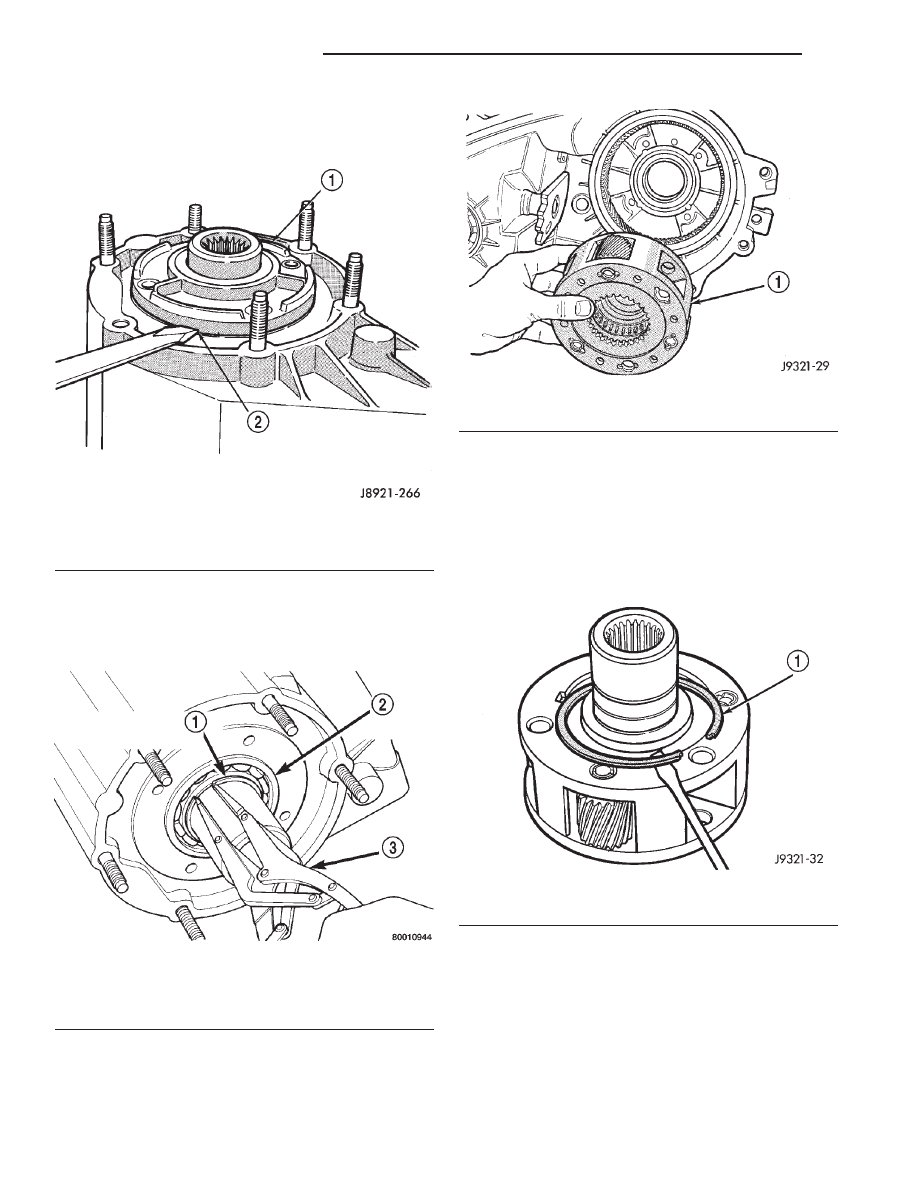
(2) Remove front bearing retainer. Pry retainer

loose with pry tool positioned in slots at each end of
retainer (Fig. 32).

(3) Remove front bearing retainer seal. Tap seal

out with drift and hammer.

(4) Remove input gear retaining ring with heavy

duty snap ring pliers (Fig. 33)

(5) Place front case in horizontal position. Then

remove input gear and low range gear as an assem-
bly (Fig. 34). Tap gear out of bearing with plastic
mallet if necessary.

INPUT AND LOW RANGE GEAR DISASSEMBLY

(1) Remove snap-ring that retains input gear in

low range gear (Fig. 35).

(2) Remove retainer (Fig. 36).
(3) Remove front tabbed thrust washer (Fig. 37).
(4) Remove input gear (Fig. 38).
(5) Remove rear tabbed thrust washer from low

range gear (Fig. 39).

Fig. 32 Front Bearing Retainer Removal

1 – FRONT BEARING RETAINER
2 – RETAINER SLOT

Fig. 33 Removing Input Gear Retaining ring

1 – INPUT GEAR BEARING RETAINING RING
2 – INPUT GEAR BEARING
3 – SNAP RING PLIERS

Fig. 34 Input Gear And Planetary Carrier Removal

1 – INPUT AND LOW RANGE GEAR ASSEMBLY

Fig. 35 Input Gear Snap-Ring Removal

1 – INPUT GEAR SNAP RING

21 - 426

NV231 TRANSFER CASE

DN

DISASSEMBLY AND ASSEMBLY (Continued)

Fig. 36 Input Gear Retainer Removal

1 – INPUT GEAR
2 – LOW RANGE GEAR
3 – RETAINER

Fig. 37 Front Tabbed Thrust Washer Removal

1 – FRONT TABBED THRUST WASHER

Fig. 38 Input Gear Removal

1 – INPUT GEAR
2 – LOW RANGE GEAR

Fig. 39 Rear Tabbed Thrust Washer Removal

1 – LOW RANGE GEAR
2 – REAR TABBED THRUST WASHER

DN

NV231 TRANSFER CASE

21 - 427

DISASSEMBLY AND ASSEMBLY (Continued)

ASSEMBLY

Lubricate transfer case components with Mopar

t

Dexron II automatic transmission fluid or petroleum
jelly (where indicated) during assembly.

BEARING AND SEAL INSTALLATION

CAUTION: The bearing bores in various transfer
case components contain oil feed holes. Make sure
replacement bearings do not block the holes.

(1) Remove seal from case with pry tool (Fig. 40).
(2) Remove bearing retaining ring with screw-

driver (Fig. 41).

(3) Remove bearing with Tool Handle C-4171 and

Tool 5065 (Fig. 42).

(4) Install front output shaft front bearing in case

with Tool Handle C-4171 and Installer 5064 (Fig. 43).

Fig. 40 Front Output Seal Removal

1 – OUTPUT SHAFT SEAL
2 – PRYBAR

Fig. 41 Front Output Shaft Bearing Retaining Ring

Removal

1 – SCREWDRIVERS
2 – SNAP RING
3 – FRONT OUTPUT SHAFT BEARING
4 – FRONT CASE

Fig. 42 Front Output Shaft Bearing Removal

1 – FRONT CASE
2 – SPECIAL TOOL C-4171
3 – SPECIAL TOOL 5065

Fig. 43 Front Output Shaft Bearing Installation

1 – SPECIAL TOOL C-4171
2 – SPECIAL TOOL 5064

21 - 428

NV231 TRANSFER CASE

DN

DISASSEMBLY AND ASSEMBLY (Continued)

(5) Install output shaft front bearing retaining

ring (Fig. 44). Start ring into place by hand. Then
use small screwdriver to work ring into case groove.
Be sure ring is fully seated before proceeding.

(6) Install new front output seal in front case with

Installer Tool 8143 as follows:

(a) Place new seal on tool. Garter spring on

seal goes toward interior of case.

(b) Start seal in bore with light taps from ham-

mer (Fig. 45). Once seal is started, continue tap-
ping seal into bore until installer tool bottoms
against case.

(7) Remove the output shaft rear bearing with the

screw and jaws from Remover L-4454 and Cup 8148
(Fig. 46).

(8) Install new bearing with Tool Handle C-4171

and Installer 5066 (Fig. 47). The bearing bore is
chamfered at the top. Install the bearing so it is
flush with the lower edge of this chamfer (Fig. 48).

Fig. 44 Installing Output Shaft Front Bearing

Retaining Ring

1 – WORK RETAINING RING INTO BORE GROOVE WITH SMALL

SCREWDRIVER

Fig. 45 Front Output Seal Installation

1 – INSTALLER 8143
2 – TRANSFER CASE

Fig. 46 Output Shaft Rear Bearing Removal

1 – REAR CASE
2 – SPECIAL TOOL L-4454–1 AND L-4454–3
3 – SPECIAL TOOL 8148

Fig. 47 Output Shaft Rear Bearing Installation

1 – HANDLE C-4171
2 – OUTPUT SHAFT INNER BEARING
3 – INSTALLER 5066

DN

NV231 TRANSFER CASE

21 - 429

DISASSEMBLY AND ASSEMBLY (Continued)


Content   ..  138  139  140  141   ..