Dodge Durango (DN). Manual - part 127
 

  Index      Dodge     Dodge Durango (DN) - service repair manual 2000 year


Search            


Content   ..  125  126  127  128   ..


Dodge Durango (DN). Manual - part 127


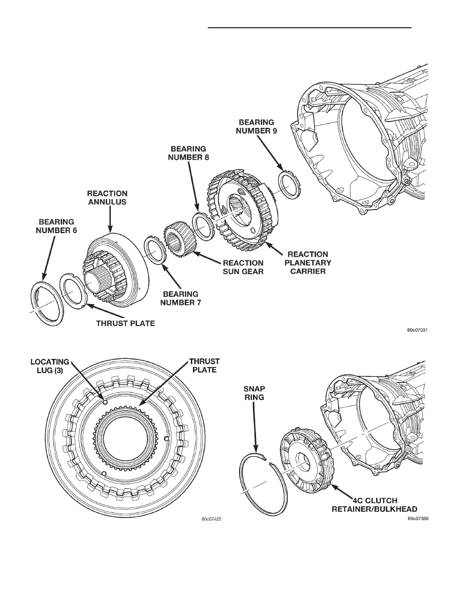
sure that the open ends of the snap-ring are located
in the case opening toward the valve body area.

(36) Air check the 2C and 4C clutch operation.

(37) Using Alignment Plate 8261, Adapter 8266-17

from End-Play Tool Set 8266, and Dial Indicator
C-3339, measure and record the output shaft end-
play (Fig. 80). The correct output shaft end-play is

Fig. 77 Install Reaction Annulus and Carrier

Fig. 78 Thrust Plate Alignment

Fig. 79 Install 4C Clutch Retainer/Bulkhead

21 - 374

45RFE AUTOMATIC TRANSMISSION

DN

DISASSEMBLY AND ASSEMBLY (Continued)

0.53–0.78 mm (0.021–0.031 in.). Adjust as necessary.
Install the chosen output shaft selective spacer and
re-measure end-play to verify selection.

(38) Apply a bead of RTV silicone and install the

extension/adapter housing onto the transmission
case.

(39) Install and torque the bolts to hold the exten-

sion/adapter housing onto the transmission case. The
correct torque is 54 N·m (40 ft.lbs.).

(40) Install the number 5 bearing and spacer onto

the 4C retainer/bulkhead (Fig. 81).

(41) Install the input clutch assembly into the

transmission case (Fig. 81). Make sure that the input
clutch assembly is fully installed by performing a
visual inspection through the input speed sensor

hole. If the tone wheel on the input clutch assembly
is visible, the assembly is fully installed.

(42) Install the number 1 bearing with the flat

side down in the pocket of the input clutch assembly
(Fig. 81).

(43) Install the oil pump into the transmission

case (Fig. 82).

(44) Install the bolts to hold the oil pump into the

transmission case. Tighten the oil pump bolts to 28
N·m (250 in.lbs.).

(45) Using Adapter 8266-1 from End-Play Tool Set

8266 and Dial Indicator C-3339, measure and record
the input shaft end-play (Fig. 83). The correct end-
play is 0.79–1.07 mm (0.031–0.042 in.). Adjust as
necessary. Install the chosen spacer on the number 5
bearing and re-measure end-play to verify selection.

NOTE: When measuring the input shaft end-play,
two “stops” will be felt. When the input shaft is
pushed inward and the dial indicator zeroed, the
first

(

stop” felt when the input shaft is pulled out-

ward is the movement of the input shaft in the input
clutch housing hub. This value should not be
included in the end-play measured value and there-
fore must be recorded and subtracted from the dial
indicator reading.

(46) Install the transmission front cover into the

transmission case (Fig. 84).

(47) Install the outer snap-ring to hold the trans-

mission front cover into the transmission case (Fig.
84).

(48) Partially install the inner transmission front

cover snap-ring onto the oil pump (Fig. 84).

Fig. 81 Install Input Clutch Assembly

Fig. 80 Measure Output Shaft End Play

Fig. 82 Install Oil Pump

DN

45RFE AUTOMATIC TRANSMISSION

21 - 375

DISASSEMBLY AND ASSEMBLY (Continued)

(49) Using Installer 8255, install the inner trans-

mission front cover snap-ring the remainder of the
way onto the oil pump (Fig. 85).

(50) Install the valve body (Fig. 86). Tighten the

valve body to transmission case bolts to 12 N·m (105
in.lbs.).

(51) Install the primary oil filter and the oil cooler

filter (Fig. 87). Tighten the screws to hold the pri-
mary oil filter to the valve body to 4.5 N·m (40
in.lbs.). Using Oil Filter Wrench 8321, tighten the
cooler return oil filter to the transmission case to 14
N·m (125 in.lbs.).

(52) Apply RTV silicone to the oil pan and install

the transmission oil pan. Tighten the bolts to 12 N·m
(105 in.lbs.).

(53) Install the input, output, and line pressure

sensors (Fig. 88). Tighten the bolts to 12 N·m (105
in.lbs.).

(54) Install the manual shift lever from the trans-

mission. Torque the retaining cross-bolt to 16 N·m
(140 in.lbs.).

VALVE BODY

DISASSEMBLY

(1) Remove the screws holding the solenoid and

pressure switch assembly to the valve body (Fig. 89).
Do not remove the screws on the top of the solenoid
and pressure switch assembly.

Fig. 83 Measure Input Shaft End Play

Fig. 84

Fig. 85 Seat Snap Ring Using Tool 8255

Fig. 86 Install Valve Body Assembly

21 - 376

45RFE AUTOMATIC TRANSMISSION

DN

DISASSEMBLY AND ASSEMBLY (Continued)

(2) Separate the solenoid and pressure switch

assembly from the valve body.

(3) Remove the screw holding the detent spring

(Fig. 90) onto the valve body.

(4) Remove the detent spring from the valve body.
(5) Remove the TRS selector plate from the valve

body and the manual valve.

(6) Remove the clutch passage seals from the valve

body, if necessary.

(7) Remove the screws holding the accumulator

cover onto the valve body (Fig. 91).

(8) Remove the accumulator springs and pistons

from the valve body. Note which accumulator piston
and spring belong in each location.

(9) Place the valve body on the bench with the

transfer plate upward.

NOTE: The valve body contains seven check balls.
The transfer plate must be placed upward to pre-

vent losing the check balls when the transfer plate
is removed from the valve body.

(10) Remove the screws holding the valve body to

the valve body transfer plate.

(11) Remove the transfer plate from the valve

body. Note the location of all check balls (Fig. 92).

(12) Remove the check balls from the valve body.
(13) Remove the retainers securing the solenoid

switch valve, manual valve, and the low/reverse
switch valve into the valve body and remove the
associated valve and spring. Tag each valve and
spring combination with location information to aid
in assembly.

Fig. 87 Install Primary Oil and Cooler Filters

Fig. 88 Install Input, Output, and Line Pressure

Sensors

Fig. 89 Solenoid and Pressure Switch Assembly

Screws

Fig. 90 Valve Body External Components

DN

45RFE AUTOMATIC TRANSMISSION

21 - 377

DISASSEMBLY AND ASSEMBLY (Continued)


Content   ..  125  126  127  128   ..