Dodge Durango (DN). Manual - part 96
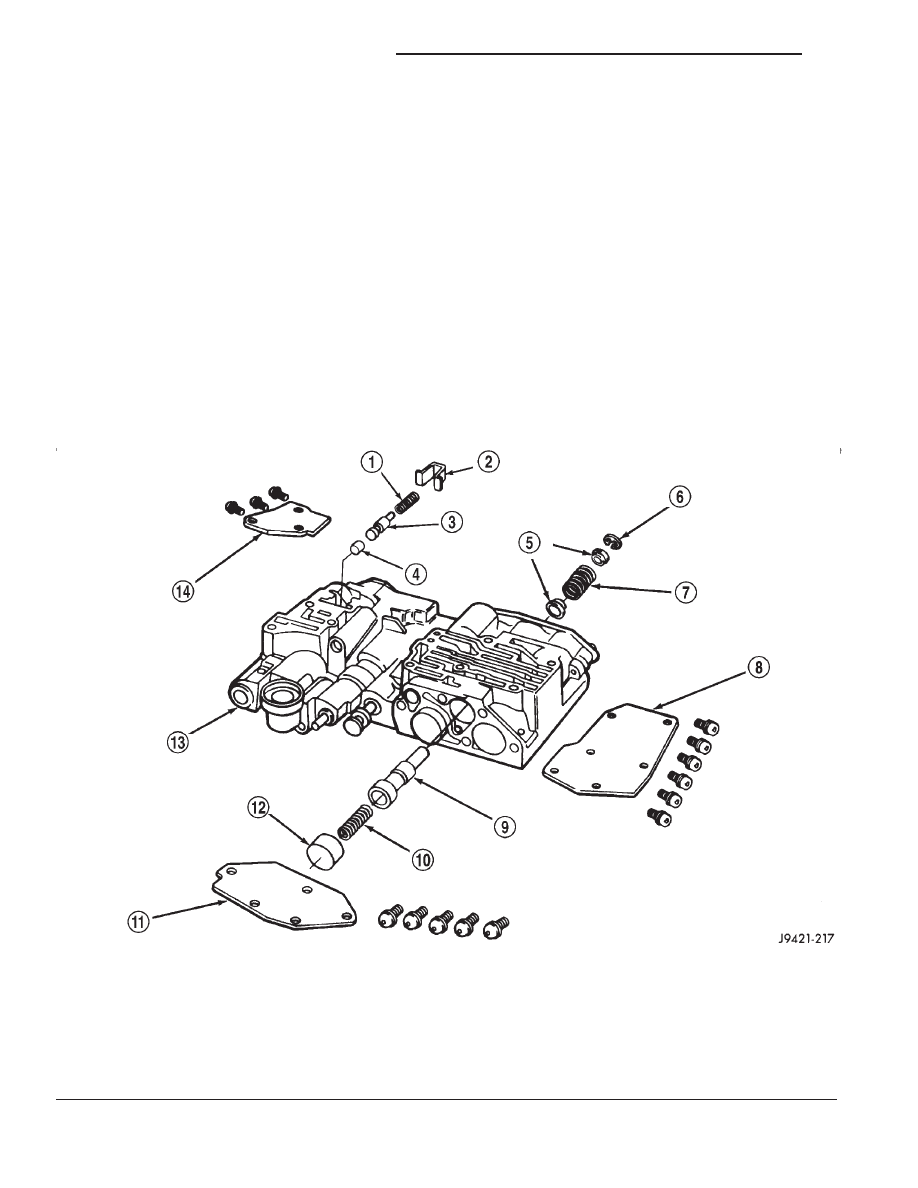
UPPER HOUSING VALVE AND PLUG
Refer to (Fig. 136), (Fig. 137) and (Fig. 138) to per-
form the following steps.
(1) Lubricate valves, plugs, springs with clean
transmission fluid.
(2) Assemble regulator valve line pressure plug,
sleeve, throttle plug and spring. Insert assembly in
upper housing and install cover plate. Tighten cover
plate screws to 4 N·m (35 in. lbs.) torque.
(3) Install 1-2 and 2-3 shift valves and springs.
(4) Install 1-2 shift control valve and spring.
(5) Install retainer, spring, limit valve, and 2-3
throttle plug from limit valve housing.
(6) Install limit valve housing and cover plate.
Tighten screws to 4 N·m (35 in. lbs.).
(7) Install shuttle valve as follows:
(a) Insert plastic guides in shuttle valve second-
ary spring and install spring on end of valve.
(b) Install shuttle valve into housing.
(c) Hold shuttle valve in place.
(d) Compress secondary spring and install E-clip
in groove at end of shuttle valve.
(e) Verify that spring and E-clip are properly
seated before proceeding.
(8) Install shuttle valve cover plate. Tighten cover
plate screws to 4 N·m (35 in. lbs.) torque.
(9) Install 1-2 and 2-3 valve governor plugs in
valve body.
(10) Install shuttle valve primary spring and
throttle plug.
(11) Align and install governor plug cover. Tighten
cover screws to 4 N·m (35 in. lbs.) torque.
Fig. 136 Shuttle And Boost Valve Components
1 – SPRING
2 – RETAINER
3 – BOOST VALVE
4 – BOOST VALVE PLUG
5 – SPRING GUIDES
6 – E-CLIP
7 – SHUTTLE VALVE SECONDARY SPRING
8 – SHUTTLE VALVE COVER
9 – SHUTTLE VALVE
10 – SHUTTLE VALVE PRIMARY SPRING
11 – GOVERNOR PLUG COVER
12 – THROTTLE PLUG
13 – UPPER HOUSING
14 – BOOST VALVE COVER
21 - 250
46RE AUTOMATIC TRANSMISSION
DN
DISASSEMBLY AND ASSEMBLY (Continued)