Dodge Durango (DN). Manual - part 75
 

  Index      Dodge     Dodge Durango (DN) - service repair manual 2000 year


Search            


Content   ..  73  74  75  76   ..


Dodge Durango (DN). Manual - part 75


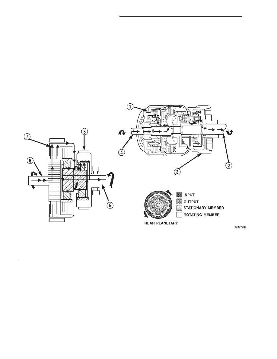
REVERSE POWERFLOW

When the gear selector is moved into the reverse

position (Fig. 5), the front clutch and the rear band
are applied. With the application of the front clutch,
engine torque is applied to the sun gear, turning it in
a clockwise direction. The clockwise rotation of the
sun gear causes the rear planet pinions to rotate
against engine rotation in a counterclockwise direc-
tion. The rear band is holding the low reverse drum,
which is splined to the rear carrier. Since the rear
carrier is being held, the torque from the planet pin-
ions is transferred to the rear annulus gear, which is

splined to the output shaft. The output shaft in turn
rotates with the annulus gear in a counterclockwise
direction giving a reverse gear output. The entire
transmission of torque is applied to the rear plane-
tary gearset only. Although there is torque input to
the front gearset through the sun gear, no other
member of the gearset is being held. During the
entire reverse stage of operation, the front planetary
gears are in an idling condition.

Fig. 5 Reverse Powerflow

1 – FRONT CLUTCH ENGAGED
2 – OUTPUT SHAFT
3 – LOW/REVERSE BAND APPLIED
4 – INPUT SHAFT

5 – OUTPUT SHAFT
6 – INPUT SHAFT
7 – FRONT CLUTCH ENGAGED
8 – LOW/REVERSE BAND APPLIED

21 - 166

46RE AUTOMATIC TRANSMISSION

DN

DESCRIPTION AND OPERATION (Continued)

FIRST GEAR POWERFLOW

When the gearshift lever is moved into the drive

position the transmission goes into first gear (Fig. 6).
As soon as the transmission is shifted from park or
neutral to drive, the rear clutch applies, applying the
rear clutch pack to the front annulus gear. Engine
torque is now applied to the front annulus gear turn-
ing it in a clockwise direction. With the front annulus
gear turning in a clockwise direction, it causes the
front planets to turn in a clockwise direction. The
rotation of the front planets cause the sun to revolve
in a counterclockwise direction. The sun gear now
transfers its counterclockwise rotation to the rear
planets which rotate back in a clockwise direction.
With the rear annulus gear stationary, the rear
planet rotation on the annulus gear causes the rear
planet carrier to revolve in a counterclockwise direc-
tion. The rear planet carrier is splined into the low-
reverse drum, and the low reverse drum is splined to
the inner race of the over-running clutch. With the
over-running clutch locked, the planet carrier is held,
and the resulting torque provided by the planet pin-
ions is transferred to the rear annulus gear. The rear
annulus gear is splined to the output shaft and
rotated along with it (clockwise) in an underdrive
gear reduction mode.

SECOND GEAR POWERFLOW

In drive-second (Fig. 7), the same elements are

applied as in manual-second. Therefore, the power
flow will be the same, and both gears will be dis-
cussed as one in the same. In drive-second, the trans-
mission has proceeded from first gear to its shift
point, and is shifting from first gear to second. The
second gear shift is obtained by keeping the rear
clutch applied and applying the front (kickdown)
band. The front band holds the front clutch retainer
that is locked to the sun gear driving shell. With the
rear clutch still applied, the input is still on the front
annulus gear turning it clockwise at engine speed.
Now that the front band is holding the sun gear sta-
tionary, the annulus rotation causes the front planets
to rotate in a clockwise direction. The front carrier is
then also made to rotate in a clockwise direction but
at a reduced speed. This will transmit the torque to
the output shaft, which is directly connected to the
front planet carrier. The rear planetary annulus gear
will also be turning because it is directly splined to
the output shaft. All power flow has occurred in the
front planetary gear set during the drive-second
stage of operation, and now the over-running clutch,
in the rear of the transmission, is disengaged and
freewheeling on its hub.

Fig. 6 First Gear Powerflow

1 – OUTPUT SHAFT
2 – OVER-RUNNING CLUTCH HOLDING
3 – REAR CLUTCH APPLIED
4 – OUTPUT SHAFT

5 – OVER-RUNNING CLUTCH HOLDING
6 – INPUT SHAFT
7 – REAR CLUTCH APPLIED
8 – INPUT SHAFT

DN

46RE AUTOMATIC TRANSMISSION

21 - 167

DESCRIPTION AND OPERATION (Continued)

DIRECT DRIVE POWERFLOW

The vehicle has accelerated and reached the shift

point for the 2–3 upshift into direct drive (Fig. 8).
When the shift takes place, the front band is
released, and the front clutch is applied. The rear
clutch stays applied as it has been in all the forward
gears. With the front clutch now applied, engine
torque is now on the front clutch retainer, which is
locked to the sun gear driving shell. This means that
the sun gear is now turning in engine rotation (clock-
wise) and at engine speed. The rear clutch is still
applied so engine torque is also still on the front
annulus gear. If two members of the same planetary
set are driven, direct drive results. Therefore, when
two members are rotating at the same speed and in
the same direction, it is the same as being locked up.
The rear planetary set is also locked up, given the
sun gear is still the input, and the rear annulus gear
must turn with the output shaft. Both gears are
turning in the same direction and at the same speed.
The front and rear planet pinions do not turn at all
in direct drive. The only rotation is the input from

the engine to the connected parts, which are acting
as one common unit, to the output shaft.

FOURTH GEAR POWERFLOW

Fourth gear overdrive range is electronically con-

trolled and hydraulically activated. Various sensor
inputs are supplied to the powertrain control module
to operate the overdrive solenoid on the valve body.
The solenoid contains a check ball that opens and
closes a vent port in the 3-4 shift valve feed passage.
The overdrive solenoid (and check ball) are not ener-
gized in first, second, third, or reverse gear. The vent
port remains open, diverting line pressure from the
2-3 shift valve away from the 3-4 shift valve. The
overdrive control switch must be in the ON position
to transmit overdrive status to the PCM. A 3-4
upshift occurs only when the overdrive solenoid is
energized by the PCM. The PCM energizes the over-
drive solenoid during the 3-4 upshift. This causes the
solenoid check ball to close the vent port allowing
line pressure from the 2-3 shift valve to act directly
on the 3-4 upshift valve. Line pressure on the 3-4
shift valve overcomes valve spring pressure moving
the valve to the upshift position. This action exposes

Fig. 7 Second Gear Powerflow

1 – KICKDOWN BAND APPLIED
2 – OUTPUT SHAFT
3 – REAR CLUTCH ENGAGED
4 – OUTPUT SHAFT
5 – OVER-RUNNING CLUTCH FREE-WHEELING

6 – INPUT SHAFT
7 – REAR CLUTCH APPLIED
8 – KICKDOWN BAND APPLIED
9 – INPUT SHAFT

21 - 168

46RE AUTOMATIC TRANSMISSION

DN

DESCRIPTION AND OPERATION (Continued)

the feed passages to the 3-4 timing valve, 3-4 quick
fill valve, 3-4 accumulator, and ultimately to the
overdrive piston. Line pressure through the timing
valve moves the overdrive piston into contact with
the overdrive clutch. The direct clutch is disengaged
before the overdrive clutch is engaged. The boost
valve provides increased fluid apply pressure to the
overdrive clutch during 3-4 upshifts, and when accel-
erating in fourth gear. The 3-4 accumulator cushions
overdrive clutch engagement to smooth 3-4 upshifts.
The accumulator is charged at the same time as
apply pressure acts against the overdrive piston.

FLUID

NOTE: Refer

to

the

maintenance

schedules

in

Group 0, Lubrication and Maintenance for the rec-
ommended maintenance (fluid/filter change) inter-
vals for this transmission.

NOTE: Refer to Service Procedures in this group
for fluid level checking procedures.

DESCRIPTION

Mopar

t ATF Plus 3, Type 7176, automatic trans-

mission fluid is the recommended fluid for Daimler-
Chrysler automatic transmissions.

Dexron II fluid IS NOT recommended. Clutch

chatter can result from the use of improper
fluid.

Mopar

t ATF Plus 3, Type 7176, automatic trans-

mission fluid when new is red in color. The ATF is
dyed red so it can be identified from other fluids used
in the vehicle such as engine oil or antifreeze. The
red color is not permanent and is not an indicator of
fluid condition. As the vehicle is driven, the ATF will
begin to look darker in color and may eventually
become brown. This is normal. A dark brown/black
fluid accompanied with a burnt odor and/or deterio-
ration in shift quality may indicate fluid deteriora-
tion or transmission component failure.

FLUID ADDITIVES

DaimlerChrysler strongly recommends against the

addition of any fluids to the transmission, other than
those automatic transmission fluids listed above.

Fig. 8 Direct Drive Powerflow

1 – FRONT CLUTCH APPLIED
2 – OVER-RUNNING CLUTCH FREE-WHEELING
3 – OUTPUT SHAFT
4 – REAR CLUTCH APPLIED
5 – OUTPUT SHAFT

6 – INPUT SHAFT
7 – OVER-RUNNING CLUTCH FREE-WHEELING
8 – REAR CLUTCH APPLIED
9 – FRONT CLUTCH APPLIED
10 – INPUT SHAFT

DN

46RE AUTOMATIC TRANSMISSION

21 - 169

DESCRIPTION AND OPERATION (Continued)


Content   ..  73  74  75  76   ..