Dodge Durango (DN). Manual - part 68
FRONT SERVO
Clean the servo piston components with solvent
and dry them with compressed air. Wipe the band
clean with lint free shop towels.
Replace the front band if distorted, lining is
burned, flaking off, or worn to the point where the
grooves in the lining material are no longer visible.
Inspect the servo components. Replace the springs
if collapsed, distorted or broken. Replace the guide,
rod and piston if cracked, bent, or worn. Discard the
servo snap ring if distorted or warped.
Check the servo piston bore for wear. If the bore is
severely scored, or damaged, it will be necessary to
replace the case.
Replace any servo component if doubt exists about
condition. Do not reuse suspect parts.
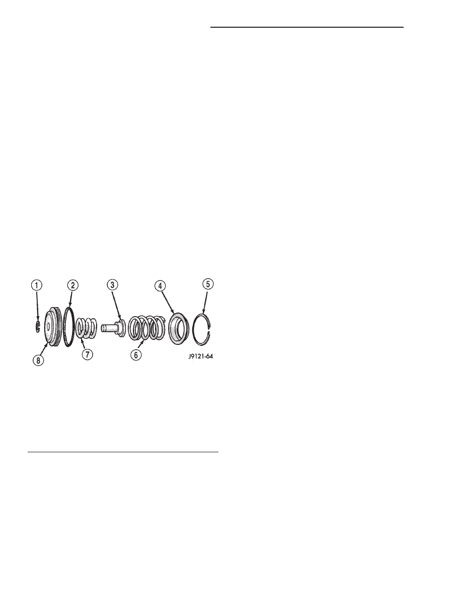
REAR SERVO
Remove and discard the servo piston seal ring (Fig.
304). Then clean the servo components with solvent
and dry with compressed air. Replace either spring if
collapsed, distorted or broken. Replace the plug and
piston if cracked, bent, or worn. Discard the servo
snap rings and use a new ones at assembly.
OIL PUMP AND REACTION SHAFT SUPPORT
(1) Clean pump and support components with sol-
vent and dry them with compressed air.
(2) Check condition of the seal rings and thrust
washer on the reaction shaft support. The seal rings
do not need to be replaced unless cracked, broken, or
severely worn.
(3) Inspect the pump and support components.
Replace the pump or support if the seal ring grooves
or machined surfaces are worn, scored, pitted, or
damaged. Replace the pump gears if pitted, worn
chipped, or damaged.
(4) Inspect the pump bushing. Then check the
reaction shaft support bushing. Replace either bush-
ing only if heavily worn, scored or damaged. It is not
necessary to replace the bushings unless they are
actually damaged.
(5) Install the gears in the pump body and mea-
sure pump component clearances as follows:
(a) Clearance between outer gear and reaction
shaft housing should be 0.010 to 0.063 mm (0.0004
to 0.0025 in.). Clearance between inner gear and
reaction shaft housing should be 0.010 to 0.063
mm (0.0004 to 0.0025 in.). Both clearances can be
measured at the same time by:
(I) Installing the pump gears in the pump
housing.
(II) Position an appropriate piece of Plasti-
gage
y across both gears.
(III) Align the plastigage to a flat area on the
reaction shaft housing.
(IV) Install the reaction shaft to the pump
housing.
(V) Separate the reaction shaft housing from
the pump housing and measure the Plastigage
y
following the instructions supplied with it.
(b) Clearance between inner gear tooth and
outer gear should be 0.08 to 0.19 mm (0.0035 to
0.0075 in.). Measure clearance with an appropriate
feeler gauge.
(c) Clearance between outer gear and pump
housing should also be 0.010 to 0.19 mm (0.0035 to
0.0075 in.). Measure clearance with an appropriate
feeler gauge.
FRONT CLUTCH
Clean and inspect the front clutch components.
Replace the clutch discs if warped, worn, scored,
burned or charred, or if the facing is flaking off.
Replace the steel plates if heavily scored, warped, or
broken. Be sure the driving lugs on the plates are in
good condition. The lugs must not be bent, cracked or
damaged in any way.
Replace the clutch spring and spring retainer if
either is distorted, warped or broken.
Check the lug grooves in the clutch retainer. The
steel plates should slide freely in the slots. Replace
the retainer if the grooves are worn or damaged.
Check action of the check ball in the retainer (Fig.
305). The ball must move freely and not stick.
NOTE: Inspect the clutch retainer bushings care-
fully (Fig. 306). The retainer bushings are NOT ser-
viceable. It will be necessary to replace the retainer
if either bushing is scored, or worn.
Fig. 304 Rear Servo Components
1 – SNAP RING
2 – PISTON SEAL
3 – PISTON PLUG
4 – SPRING RETAINER
5 – SNAP RING
6 – PISTON SPRING
7 – CUSHION SPRING
8 – PISTON
21 - 138
42/44RE AUTOMATIC TRANSMISSION
DN
CLEANING AND INSPECTION (Continued)