Dodge Durango (DN). Manual - part 44
GOVERNOR PRESSURE SENSOR
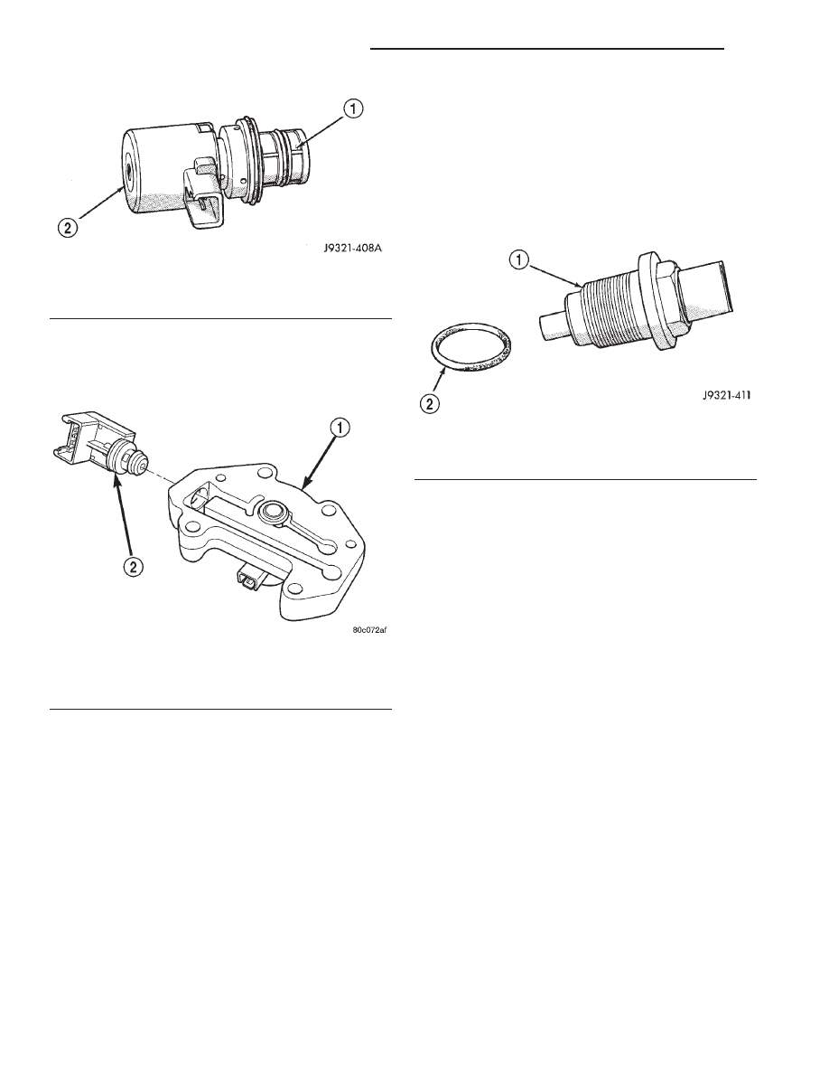
The governor pressure sensor measures output
pressure of the governor pressure solenoid valve (Fig.
64).
GOVERNOR BODY AND TRANSFER PLATE
The transfer plate is designed to supply transmis-
sion line pressure to the governor pressure solenoid
valve and to return governor pressure.
The governor pressure solenoid valve is mounted in
the governor body. The body is bolted to the lower
side of the transfer plate (Fig. 64).
TRANSMISSION FLUID TEMPERATURE THERMISTOR
Transmission fluid temperature readings are sup-
plied to the transmission control module by the ther-
mistor. The temperature readings are used to control
engagement of the fourth gear overdrive clutch, the
converter clutch, and governor pressure. Normal
resistance value for the thermistor at room tempera-
ture is approximately 1000 ohms.
The thermistor is part of the governor pressure
sensor assembly and is immersed in transmission
fluid at all times.
TRANSMISSION SPEED SENSOR
The speed sensor (Fig. 65) is located in the over-
drive gear case. The sensor is positioned over the
park gear and monitors transmission output shaft
rotating speed.
OPERATION
Compensation is required for performance varia-
tions of two of the input devices. Though the slope of
the transfer functions is tightly controlled, offset may
vary due to various environmental factors or manu-
facturing tolerances.
The pressure transducer is affected by barometric
pressure as well as temperature. Calibration of the
zero pressure offset is required to compensate for
shifting output due to these factors.
Normal calibration will be performed when sump
temperature is above 50 degrees F, or in the absence
of sump temperature data, after the first 10 minutes
of vehicle operation. Calibration of the pressure
transducer offset occurs each time the output shaft
speed falls below 200 RPM. Calibration shall be
repeated each 3 seconds the output shaft speed is
below 200 RPM. A.5 second pulse of 95% duty cycle
is applied to the governor pressure solenoid valve
and the transducer output is read during this pulse.
Averaging of the transducer signal is necessary to
reject electrical noise.
Under cold conditions (below 50 degrees F sump),
the governor pressure solenoid valve response may
be too slow to guarantee 0 psi during the.5 second
calibration pulse. Calibration pulses are continued
during this period, however the transducer output
valves are discarded. Transducer offset must be read
at key-on, under conditions which promote a stable
reading. This value is retained and becomes the off-
set during the “cold” period of operation.
Fig. 63 Governor Pressure Solenoid Valve
1 – SOLENOID FILTER
2 – GOVERNOR PRESSURE SOLENOID
Fig. 64 Governor Pressure Sensor
1 – GOVERNOR BODY
2 – GOVERNOR PRESSURE SENSOR/TRANSMISSION FLUID
TEMPERATURE THERMISTOR
Fig. 65 Transmission Output Speed Sensor
1 – TRANSMISSION OUTPUT SHAFT SPEED SENSOR
2 – SEAL
21 - 42
42/44RE AUTOMATIC TRANSMISSION
DN
DESCRIPTION AND OPERATION (Continued)