Dodge Durango (DN). Manual - part 18
firmly connected to distributor cap and coil. Be sure
camshaft position sensor wire connector (at the dis-
tributor) is firmly connected to harness connector.
Inspect spark plug condition. Refer to Group 8D,
Ignition. Connect vehicle to an oscilloscope and
inspect spark events for fouled or damaged spark
plugs or cables.
(6) Verify generator output wire, generator connec-
tor and ground wire are firmly connected to genera-
tor.
(7) Inspect system body grounds for loose or dirty
connections. Refer to Group 8, Wiring for ground
locations.
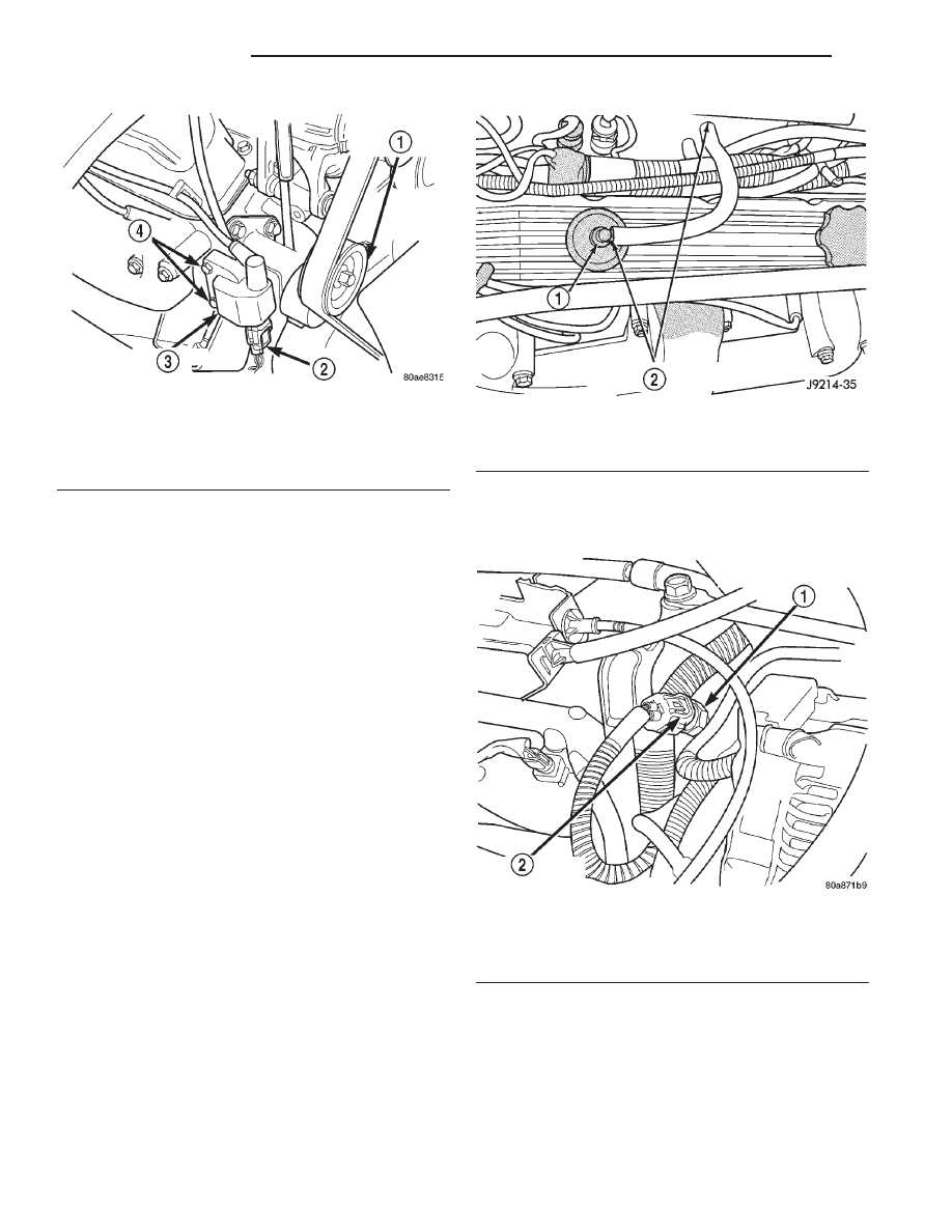
(8) Verify positive crankcase ventilation (PCV)
valve operation. Refer to Group 25, Emission Control
System for additional information. Verify PCV valve
hose is firmly connected to PCV valve and manifold
(Fig. 6).
(9) Inspect fuel tube quick-connect fitting-to-fuel
rail connections.
(10) Verify hose connections to all ports of vacuum
fittings on intake manifold are tight and not leaking.
(11) Inspect accelerator cable, transmission throt-
tle cable (if equipped) and cruise control cable con-
nections (if equipped). Check their connections to
throttle arm of throttle body for any binding or
restrictions.
(12) If equipped with vacuum brake booster, verify
vacuum booster hose is firmly connected to fitting on
intake manifold. Also check connection to brake vac-
uum booster.
(13) Inspect air cleaner inlet and air cleaner ele-
ment for dirt or restrictions.
(14) Inspect radiator grille area, radiator fins and
air conditioning condenser for restrictions.
(15) Verify intake manifold air temperature sensor
wire connector is firmly connected to harness connec-
tor (Fig. 7).
(16) Verify MAP sensor electrical connector is
firmly connected to MAP sensor (Fig. 8). Also verify
rubber L-shaped fitting from MAP sensor to throttle
body is firmly connected (Fig. 9).
(17) Verify fuel injector wire harness connectors
are firmly connected to injectors in correct order.
Each harness connector is numerically tagged with
Fig. 5 Ignition Coil
1 – ACCESSORY DRIVE BELT TENSIONER
2 – COIL CONNECTOR
3 – IGNITION COIL
4 – COIL MOUNTING BOLTS
Fig. 6 PCV Valve Hose Connections
1 – PCV VALVE
2 – PCV VALVE HOSE CONNECTIONS
Fig. 7 Intake Manifold Air Temperature Sensor—
Typical
1 – INTAKE MANIFOLD AIR TEMPERATURE SENSOR
2 – ELECTRICAL CONNECTOR
14 - 40
FUEL SYSTEM
DN
DIAGNOSIS AND TESTING (Continued)