Dodge Durango (DN). Manual - part 14
(6) Install air tube to throttle body.
THROTTLE CABLE—4.7L V-8 ENGINE
REMOVAL
CAUTION: Be careful not to damage or kink the
cable core wire (within the cable sheathing) while
servicing accelerator pedal or throttle cable.
(1) From inside vehicle, hold up accelerator pedal.
Remove plastic cable retainer (clip) and throttle cable
core wire from upper end of pedal arm (Fig. 38).
Plastic cable retainer (clip) snaps into pedal arm.
(2) Remove cable core wire at pedal arm.
(3) From inside vehicle, remove clip holding cable
to dashpanel (Fig. 38).
(4) Remove air box at throttle body.
(5) Unsnap cable from dashpanel routing clip.
(6) Remove cable housing from dash panel and
pull into engine compartment.
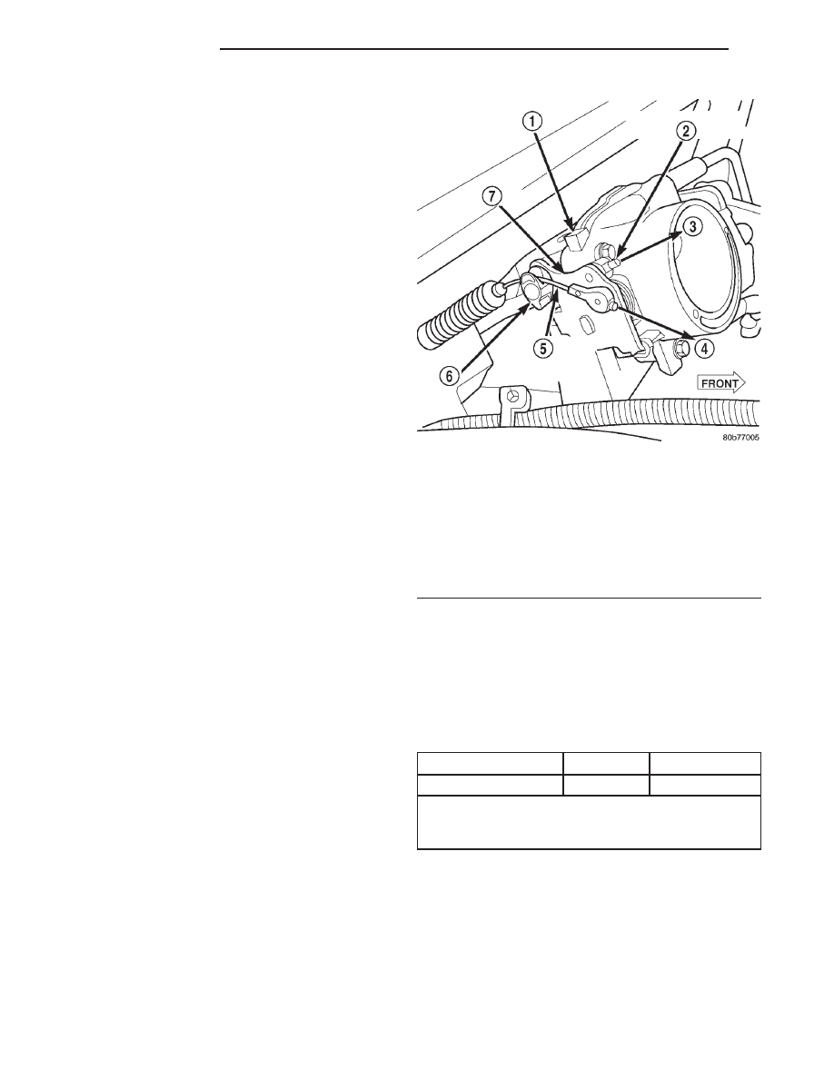
(7) Using finger pressure only, disconnect accelera-
tor cable connector at throttle body bellcrank pin by
pushing connector off bellcrank pin towards front of
vehicle (Fig. 42). DO NOT try to pull connector
off perpendicular to the bellcrank pin. Connec-
tor will be broken.
(8) Lift accelerator cable from top of cable cam
(Fig. 42).
(9) Press tab (Fig. 43) to release plastic cable
mount from bracket. Press on tab only enough to
release cable from bracket. If tab is pressed too
much, it will be broken. Slide plastic mount (Fig.
43) towards passenger side of vehicle to remove cable
from bracket.
(10) Remove throttle cable from vehicle.
INSTALLATION
(1) Slide
accelerator
cable
plastic
mount
into
bracket. Continue sliding until tab (Fig. 43) is
aligned to hole in mounting bracket.
(2) Route accelerator cable over top of cable cam.
(3) Connect cable end to throttle body bellcrank
pin (snaps on rearward).
(4) Slide rubber grommet away from plastic cable
housing.
(5) Install rubber grommet into dash panel until
seated.
(6) Push cable housing into rubber grommet and
through opening in dash panel.
(7) From inside vehicle, install clip holding cable
to dashpanel (Fig. 38).
(8) From inside vehicle, slide throttle cable core
wire into opening in top of pedal arm.
(9) Push cable retainer (clip) into pedal arm open-
ing until it snaps in place.
(10) Snap cable into dashpanel routing clip.
(11) Install air box to throttle body.
(12) Before starting engine, operate accelerator
pedal to check for any binding.
SPECIFICATIONS
FUEL TANK CAPACITY
FUEL SYSTEM PRESSURE
All Engines: 339 kPa
6 34 kPa (49.2 psi 6 5 psi)
FUEL REQUIREMENTS
Your engine is designed to meet all emissions reg-
ulations and provide excellent fuel economy and per-
formance when using high quality unleaded gasoline
having an octane rating of 87. The use of premium
Fig. 42 Accelerator Cable at Bell Crank—4.7L V-8
Engine
1 – THROTTLE BODY
2 – SPEED CONTROL CABLE CONNECTOR
3 – OFF
4 – OFF
5 – ACCELERATOR CABLE CONNECTOR
6 – CABLE CAM
7 – BELLCRANK
Models
Liters
U.S. Gallons
Standard
95
25
Nominal refill capacities are shown. A variation may
be observed from vehicle to vehicle due to
manufacturing tolerance and refill procedure.
14 - 24
FUEL SYSTEM
DN
REMOVAL AND INSTALLATION (Continued)