Dodge Dakota (R1). Manual - part 810


  Index      Dodge     Dodge Dakota (R1) - service repair manual 2000 year


Search            


Content   ..  808  809  810  811   ..


Dodge Dakota (R1). Manual - part 810


SPECIFICATIONS

SPECIFICATIONS - TORQUE - EVAP SYSTEM

DESCRIPTION

N·m

Ft. Lbs.

In. Lbs.

EVAP Canister Mounting Nut

17-24

150-210

EVAP Canister Purge Solenoid Mounting Bolt – Except 2.5L

Engine

11

95

EVAP Canister Purge Solenoid Mounting Nuts – 2.5L Engine

8

75

Leak Detection Pump (LDP) Mounting Screws

1

11

CCV HOSE

DESCRIPTION - 2.5L

2.5L 4–cylinder engines are equipped with a

Crankcase Ventilation (CCV) system. The CCV sys-
tem performs the same function as a conventional
PCV system, but does not use a vacuum controlled
valve.

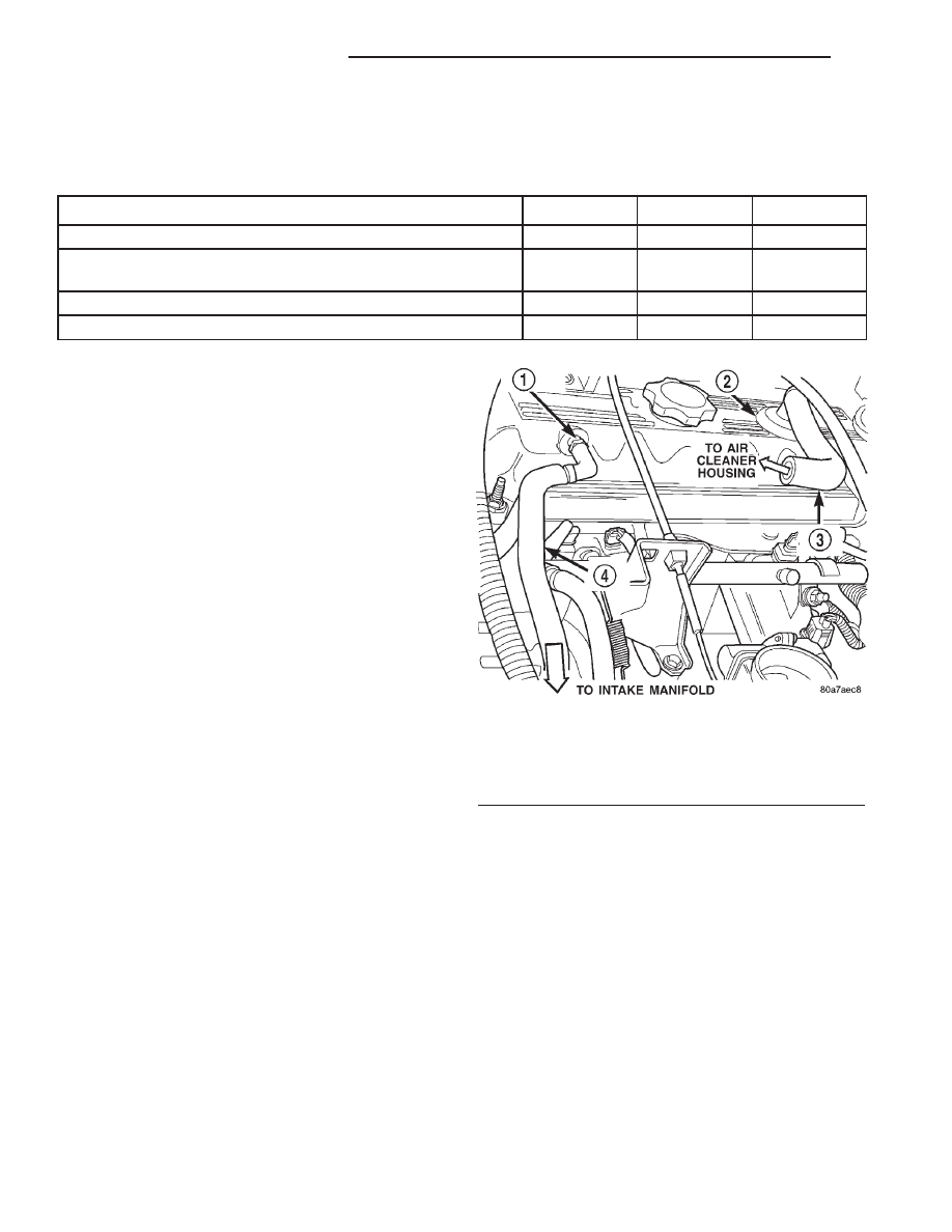
A molded vacuum tube connects a fitting on the

intake manifold to a fixed orifice fitting of a cali-
brated size. This fitting meters the amount of crank-
case vapors drawn out of the engine. The fixed orifice
fitting is located on the side of cylinder head (valve)
cover (Fig. 1).

A fresh air supply hose from the air cleaner hous-

ing is connected to a fitting at the top/rear of cylinder
head cover (Fig. 1).

When the engine is operating, fresh air enters the

engine and mixes with crankcase vapors. Engine vac-
uum draws the vapor/air mixture through the fixed
orifice and into the intake manifold. The vapors are
then consumed during engine combustion.

EVAP/PURGE SOLENOID

DESCRIPTION

The duty cycle EVAP canister purge solenoid (DCP)

regulates the rate of vapor flow from the EVAP can-
ister to the intake manifold. The Powertrain Control
Module (PCM) operates the solenoid.

During the cold start warm-up period and the hot

start time delay, the PCM does not energize the sole-
noid. When de-energized, no vapors are purged. The
PCM de-energizes the solenoid during open loop oper-
ation.

The engine enters closed loop operation after it

reaches a specified temperature and the time delay
ends. During closed loop operation, the PCM cycles
(energizes and de-energizes) the solenoid 5 or 10
times per second, depending upon operating condi-
tions. The PCM varies the vapor flow rate by chang-

ing solenoid pulse width. Pulse width is the amount
of time that the solenoid is energized. The PCM
adjusts solenoid pulse width based on engine operat-
ing condition.

REMOVAL

3.9/5.2/5.9L Engines: The duty cycle EVAP canister

purge solenoid is located at left-rear side of engine com-
partment near power brake vacuum unit (Fig. 2).

2.5L Engine: The solenoid is located at right-rear

side of engine compartment (Fig. 3).

(1) Disconnect electrical wiring connector at solenoid
(2) Disconnect vacuum harness at solenoid.
(3) Remove 2 support bracket mounting nuts.
(4) Remove solenoid and its support bracket from

vehicle.

Fig. 1 CCV System—2.5L Engine

1 - FIXED ORIFICE FITTING
2 - AIR INLET FITTING
3 - CCV TUBE
4 - CCV TUBE

25 - 24

EVAPORATIVE EMISSIONS

AN

EVAPORATIVE EMISSIONS (Continued)

INSTALLATION

3.9/5.2/5.9L Engines: The duty cycle EVAP canister

purge solenoid is located at left-rear side of engine com-
partment near power brake vacuum unit (Fig. 2).

2.5L Engine: The solenoid is located at right-rear

side of engine compartment (Fig. 3).

(1) Position EVAP canister purge solenoid and its

mounting bracket.

(2) Install mounting nuts and tighten to 8 N·m (75

in. lbs.) torque.

(3) Connect vacuum harness and wiring connector.

FUEL FILLER CAP

DESCRIPTION

The plastic fuel tank filler tube cap is threaded

onto the end of the fuel fill tube. Certain models are
equipped with a 1/4 turn cap.

OPERATION

The loss of any fuel or vapor out of fuel filler tube

is prevented by the use of a pressure-vacuum fuel fill
cap. Relief valves inside the cap will release fuel tank
pressure at predetermined pressures. Fuel tank vac-
uum will also be released at predetermined values.
This cap must be replaced by a similar unit if
replacement is necessary. This is in order for the sys-
tem to remain effective.

CAUTION: Remove fill cap before servicing any fuel
system component to relieve tank pressure. If
equipped with a California emissions package and a
Leak Detection Pump (LDP), the cap must be tight-
ened securely. If cap is left loose, a Diagnostic
Trouble Code (DTC) may be set.

REMOVAL/INSTALLATION

If replacement of the 1/4 turn fuel tank filler tube

cap is necessary, it must be replaced with an identi-
cal cap to be sure of correct system operation.

CAUTION: Remove the fuel tank filler tube cap to
relieve

fuel

tank

pressure.

The

cap

must

be

removed prior to disconnecting any fuel system
component or before draining the fuel tank.

LEAK DETECTION PUMP

DESCRIPTION

The Leak Detection Pump (LDP) is used only with

certain emission packages.

The LDP is a device used to detect a leak in the

evaporative system.

The pump contains a 3 port solenoid, a pump that

contains a switch, a spring loaded canister vent valve
seal, 2 check valves and a spring/diaphragm.

Fig. 2 Duty Cycle EVAP Canister Purge Solenoid

1 - BRACKET NUTS (2)
2 - EVAP CANISTER PURGE SOLENOID
3 - EVAP SYSTEM TEST PORT (IF EQUIPPED)
4 - VACUUM LINES
5 - ELECTRICAL CONNECTOR

Fig. 3 Duty Cycle EVAP Canister Purge Solenoid—

2.5L Engine

1 - DUTY CYCLE SOLENOID
2 - CYLINDER HEAD COVER
3 - VACUUM HOSES
4 - BRACKET NUTS (2)

AN

EVAPORATIVE EMISSIONS

25 - 25

EVAP/PURGE SOLENOID (Continued)

Immediately after a cold start, engine temperature

between 40°F and 86°F, the 3 port solenoid is briefly
energized. This initializes the pump by drawing air into
the pump cavity and also closes the vent seal. During
non-test test conditions, the vent seal is held open by
the pump diaphragm assembly which pushes it open at
the full travel position. The vent seal will remain closed
while the pump is cycling. This is due to the operation
of the 3 port solenoid which prevents the diaphragm
assembly from reaching full travel. After the brief ini-
tialization period, the solenoid is de-energized, allowing
atmospheric pressure to enter the pump cavity. This
permits the spring to drive the diaphragm which forces
air out of the pump cavity and into the vent system.
When the solenoid is energized and de-energized, the
cycle is repeated creating flow in typical diaphragm
pump fashion. The pump is controlled in 2 modes:

PUMP MODE: The pump is cycled at a fixed rate

to achieve a rapid pressure build in order to shorten
the overall test time.

TEST MODE: The solenoid is energized with a fixed

duration pulse. Subsequent fixed pulses occur when the
diaphragm reaches the switch closure point.

The spring in the pump is set so that the system will

achieve an equalized pressure of about 7.5 inches of
water.

When the pump starts, the cycle rate is quite high.

As the system becomes pressurized pump rate drops.
If there is no leak the pump will quit. If there is a
leak, the test is terminated at the end of the test
mode.

If there is no leak, the purge monitor is run. If the

cycle rate increases due to the flow through the
purge system, the test is passed and the diagnostic is
complete.

The canister vent valve will unseal the system

after completion of the test sequence as the pump
diaphragm assembly moves to the full travel position.

A typical system schematic is shown in (Fig. 4).

Fig. 4 Evaporative System Monitor Schematic—Typical

1 - DUTY CYCLE PURGE SOLENOID (DCPS) DRIVER
2 - POWERTRAIN CONTROL MODULE (PCM)
3 - 3-PORT SOLENOID DRIVER
4 - REMOTE FILTER
5 - COMBINED CANISTER VENT VALVE & LEAK DETECTION
PUMP
6 - CANISTER

7 - TANK ROLLOVER VALVE & VAPOR FLOW CONTROL ORIFICE
8 - INTAKE MANIFOLD
9 - THROTTLE BODY
10 - DCPS
11 - SWITCH SIGNAL INPUT TO THE PCM
12 - ENGINE VACUUM LINE

25 - 26

EVAPORATIVE EMISSIONS

AN

LEAK DETECTION PUMP (Continued)

REMOVAL

The LDP is located in the engine compartment

under the battery tray and Power Distribution Cen-
ter (PDC) (Fig. 5). The LDP filter is attached to the
outside of battery tray (Fig. 6). The LDP and LDP fil-
ter are replaced (serviced) as one unit.

(1) Disconnect negative battery cable at battery.
(2) Remove battery. Refer to 8, Battery for proce-

dures.

(3) Carefully disconnect rubber hose from bottom

of LDP filter (Fig. 6).

(4) Remove clip retaining LDP filter to battery

tray (Fig. 6)and remove filter from tray.

(5) Disconnect battery temperature sensor pigtail

wiring harness at bottom of battery tray.

(6) To gain access to LDP, the PDC must be par-

tially removed. Remove PDC-to-fender mounting
screw at rear of PDC. Unsnap PDC from battery
tray. To prevent damage to PDC wiring, carefully
position PDC to gain access to LDP.

(7) Remove battery tray. Refer to 8, Battery for

procedures.

(8) Carefully remove vapor/vacuum lines at LDP.
(9) Disconnect electrical connector at LDP.
(10) Remove 3 LDP mounting screws (Fig. 7) and

remove LDP from vehicle.

INSTALLATION

The LDP is located in the engine compartment

under the battery tray and Power Distribution Cen-
ter (PDC) (Fig. 5). The LDP filter is attached to the
outside of battery tray (Fig. 6). The LDP and LDP fil-
ter are replaced (serviced) as one unit.

(1) Install LDP to bottom of battery tray. Tighten

screws to 1 N·m (11 in. lbs.) torque.

(2) Carefully install vapor/vacuum lines to LDP.

The vapor/vacuum lines and hoses must be
firmly

connected.

Check

the

vapor/vacuum

lines at the LDP, LDP filter and EVAP canister

Fig. 5 Leak Detection Pump (LDP) Location

1 - BATTERY
2 - LEAK DETECTION PUMP (LDP)

Fig. 6 LDP Filter Location

1 - LDP FILTER
2 - LDP FILTER-TO-LDP HOSE
3 - BATTERY TRAY
4 - LDP MOUNTING CLIP

Fig. 7 Leak Detection Pump (LDP) Mounting Screws

1 - BATTERY TRAY
2 - LDP
3 - LDP MOUNTING SCREWS (3)

AN

EVAPORATIVE EMISSIONS

25 - 27

LEAK DETECTION PUMP (Continued)


Content   ..  808  809  810  811   ..