Dodge Dakota (R1). Manual - part 739
tor switch position is changed, or if diagnostic rou-
tines no longer allow the requested shift.
• If the driver attempts to make a shift into trans-
fer case NEUTRAL, and any of the driver controlla-
ble conditions are not met, the request will be
ignored until all of the conditions are met or until
the NEUTRAL select button is released. Additionally
the neutral lamp will flash, or begin to flash while
the button is depressed and operator controllable
conditions are not being met. All of the LED’s except
the Neutral will flash if any of the operator control-
lable conditions for shifting are not met while the
Neutral button is depressed. This
9toggle9 type of fea-
ture is necessary because the TCCM would interpret
another request immediately after the shift into
transfer case NEUTRAL has completed.
• No LED’s illuminated indicate a fault in the
transfer case control system.
SHIFT MOTOR
DESCRIPTION
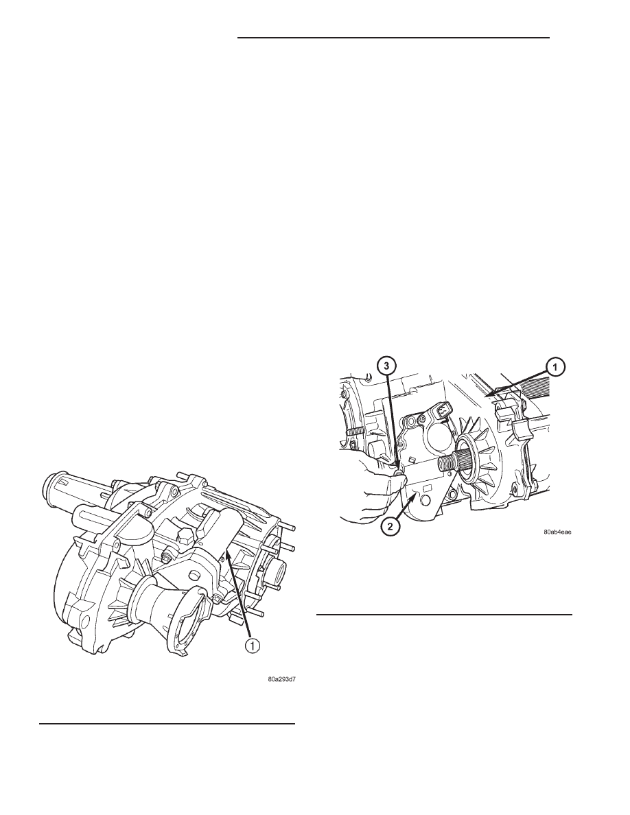
The shift motor (Fig. 90) consists of a permanent
magnet D.C. motor with gear reduction to convert a
high speed-low torque device into a low speed-high
torque device. The output of the device is coupled to
a shaft which internally moves the mode and range
forks that change the transfer case operating ranges.
The motor is rated at 25 amps maximum at 72° F
with 10 volts at the motor leads.
OPERATION
The transfer case shift motor responds to the
Transfer Case Control Module (TCCM) commands to
move the transfer case shift sector bi-directionally, as
required, to obtain the transfer case operating mode
indicated by the instrument panel mounted selector
switch.
REMOVAL
(1) Raise the vehicle on a suitable hoist.
(2) Remove the front propeller shaft. (Refer to 3 -
DIFFERENTIAL
&
DRIVELINE/PROPELLER
SHAFT/PROPELLER SHAFT - REMOVAL)
(3) Disengage the wiring connectors from the shift
motor and mode sensor.
(4) Remove the front output shaft companion
flange from the transfer case.
(5) Remove the bolts (Fig. 91) holding the shift
motor and mode sensor assembly onto the transfer
case.
(6) Separate the shift motor and mode sensor
assembly from the transfer case.
Fig. 90 Shift Motor - Shown Inverted
1 - TRANSFER CASE SHIFT MOTOR
Fig. 91 Remove the Shift Motor and Mode Sensor
Assembly Bolts
1 - TRANSFER CASE
2 - SHIFT MOTOR AND MODE SENSOR ASSEMBLY
3 - BOLT
21 - 600
TRANSFER CASE - NV244
AN
SELECTOR SWITCH (Continued)