Dodge Dakota (R1). Manual - part 734
 

  Index      Dodge     Dodge Dakota (R1) - service repair manual 2000 year


Search            


Content   ..  732  733  734  735   ..


Dodge Dakota (R1). Manual - part 734


SHIFT FORKS/HUBS/SLEEVES

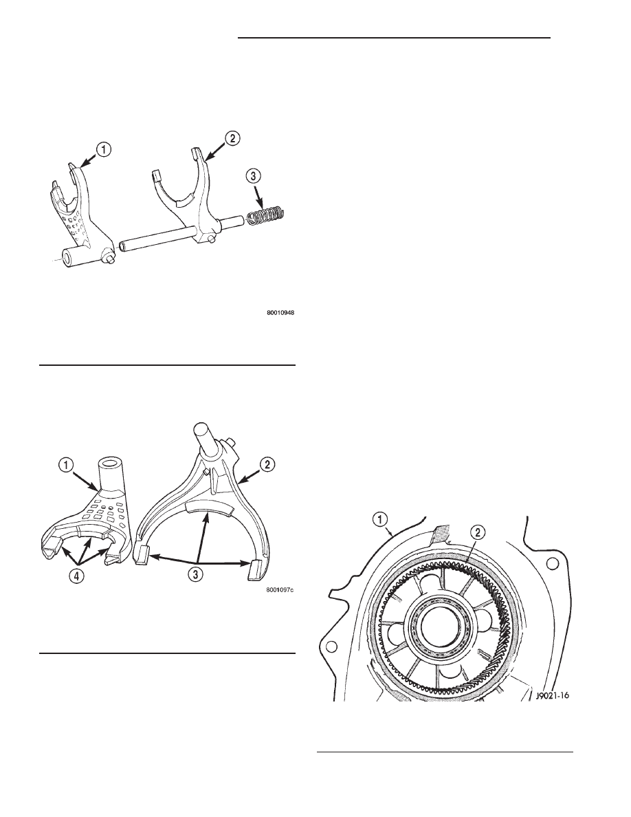
Check condition of the shift forks and mode fork

shift rail (Fig. 37). Minor nicks on the shift rail can
be smoothed with 320-400 grit emery cloth.

Inspect the shift fork wear pads (Fig. 38). The

mode and range fork pads are serviceable and can be
replaced if necessary.

Check both of the sleeves for wear or damage,

especially on the interior teeth. Replace the sleeves if
wear or damage is evident.

REAR RETAINER AND EXTENSION HOUSING

Inspect the retainer components. Replace the bear-

ing if rough or noisy. Check the retainer for cracks or
wear in the bearing bore. Clean the retainer sealing

surfaces with a scraper and 3M™ all purpose
cleaner. This will ensure proper adhesion of the
sealer during reassembly.

Inspect the retaining rings and washers. Replace

any part if distorted, bent, or broken. Reuse is not
recommended.

Inspect the extension housing seal and bushing.

Replace both components if either show any sign of
wear or damage.

FRONT OUTPUT SHAFT/FLANGE/DRIVE CHAIN

Check condition of the seal contact surfaces on the

companion flange slinger. This surface must be clean
and smooth to ensure proper seal life. Replace the
flange nut and seal washer as neither part should be
reused.

Inspect the shaft threads, sprocket teeth, and bear-

ing surfaces. Minor nicks on the teeth can be
smoothed with an oilstone. Use 320-400 grit emery to
smooth minor scratches on the shaft bearing sur-
faces. Rough threads on the shaft can be chased if
necessary. Replace the shaft if the threads are dam-
aged, bearing surfaces are scored, or if any sprocket
teeth are cracked or broken.

Examine the drive chain and shaft bearings.

Replace the chain and both sprockets if the chain is
stretched, distorted, or if any of the links bind.
Replace the bearings if rough, or noisy.

LOW RANGE ANNULUS GEAR

Inspect annulus gear condition carefully. The gear

is only serviced as part of the front case. If the gear
is damaged, it will be necessary to replace the gear
and front case as an assembly. Do not attempt to
remove the gear (Fig. 39)

Fig. 37 Shift Forks

1 - RANGE FORK
2 - MODE FORK AND RAIL
3 - MODE SPRING

Fig. 38 Shift Fork And Wear Pad Locations

1 - RANGE FORK
2 - MODE FORK
3 - WEAR PADS (SERVICEABLE)
4 - WEAR PADS (SERVICEABLE)

Fig. 39 Low Range Annulus Gear

1 - FRONT CASE
2 - LOW RANGE ANNULUS GEAR

21 - 580

TRANSFER CASE - NV244

AN

TRANSFER CASE - NV244 (Continued)

FRONT/REAR CASES AND FRONT RETAINER

Inspect the cases and retainer for wear and dam-

age. Replace the input retainer seal; do not reuse it.

Check case condition. If leaks were a problem, look

for gouges and severe scoring of case sealing sur-
faces. Also make sure the front case mounting studs
are in good condition.

Check the front case mounting studs and vent

tube. The tube can be secured with Loctite™ 271 or
680 if loose. The stud threads can be cleaned up with
a die if necessary. Also check condition of the fill/
drain plug threads in the rear case. The threads can
be repaired with a thread chaser or tap if necessary.
Or the threads can be repaired with Helicoil® stain-
less steel inserts if required.

OIL PUMP/OIL PICKUP

Examine the oil pump pickup parts. Replace the

pump if any part appears to be worn or damaged. Do
not disassemble the pump as individual parts are not
available. The pump is only available as a complete
assembly. The pickup screen, hose, and tube are the
only serviceable parts and are available separately.

ASSEMBLY

Lubricate transfer case components with automatic

transmission fluid or petroleum jelly (where indi-
cated) during assembly.

CAUTION: The bearing bores in various transfer
case components contain oil feed holes. Make sure
replacement bearings do not block the holes.

BEARINGS AND SEALS

(1) Remove snap-ring that retains front output

shaft front bearing in case (Fig. 40). Then remove
bearing. Use hammer handle, or hammer and brass
punch to tap bearing out of case.

(2) Install new front output shaft front bearing

with Tool Handle C-4171 and Installer 8033-A with
the tapered cone upward (Fig. 41).

(3) Install front bearing snap-ring (Fig. 40).

Fig. 40 Front Output Shaft Front Bearing Snap-Ring

Removal

1 - FRONT BEARING SNAP-RING

Fig. 41 Install the Front Output Shaft Front Bearing

1 - SPECIAL TOOL C-4171
2 - SPECIAL TOOL 8033-A

AN

TRANSFER CASE - NV244

21 - 581

TRANSFER CASE - NV244 (Continued)

(4) Install new front output shaft oil seal with

Installer 6952-A (Fig. 42).

(5) Remove input shaft bearing with Tool Handle

C-4171 and Remover C-4210 (Fig. 43).

(6) Install snap-ring on new input shaft bearing.
(7) Install new input shaft bearing with Tool Han-

dle C-4171 and Remover C-4210. Install bearing far
enough to seat snap-ring against case (Fig. 44).

(8) Remove the input gear pilot bearing by insert-

ing a suitably sized drift into the splined end of the
input gear and driving the bearing out with the drift
and a hammer (Fig. 45).

Fig. 45 Remove Input Gear Pilot Bearing

1 - DRIFT
2 - INPUT GEAR

Fig. 42 Install Front Output Shaft Seal - Typical

1 - INSTALLER 6952-A
2 - TRANSFER CASE

Fig. 43 Input Shaft Bearing Removal

1 - SPECIAL TOOL C-4171
2 - SPECIAL TOOL C-4210

Fig. 44 Seating Input Shaft Bearing

1 - SNAP-RING
2 - INPUT SHAFT BEARING

21 - 582

TRANSFER CASE - NV244

AN

TRANSFER CASE - NV244 (Continued)

(9) Install new pilot bearing with Installer 8128

and Handle C-4171 (Fig. 46).

(10) Install new seal in front bearing retainer with

Installer 7884 (Fig. 47).

(11) Remove front output shaft rear bearing with

the screw and jaws from Remover L-4454 and Cup
8148 (Fig. 48).

(12)

Install new bearing with Tool Handle C-4171

and Installer 5066 (Fig. 49). Lubricate bearing after
installation.

Fig. 46 Install Input Gear Pilot Bearing

1 - HANDLE C-4171
2 - INSTALLER 8128
3 - INPUT GEAR

Fig. 47 Front Bearing Retainer Seal Installation

1 - FRONT BEARING RETAINER
2 - SPECIAL TOOL 7884

Fig. 48 Remove Front Output Shaft Rear Bearing

1 - REAR CASE
2 - SPECIAL TOOL L-4454-1 AND L-4454-3
3 - SPECIAL TOOL 8148

Fig. 49 Install Front Output Shaft Rear Bearing

1 - HANDLE C-4171
2 - OUTPUT SHAFT INNER BEARING
3 - INSTALLER 5066

AN

TRANSFER CASE - NV244

21 - 583

TRANSFER CASE - NV244 (Continued)


Content   ..  732  733  734  735   ..