Dodge Dakota (R1). Manual - part 332


  Index      Dodge     Dodge Dakota (R1) - service repair manual 2000 year


Search            


Content   ..  330  331  332  333   ..


Dodge Dakota (R1). Manual - part 332


(2) Install and tighten the screws that secure the

headlamp switch. Tighten the screws to 2.2 N·m (20
in. lbs.).

(3) Reconnect the wire harness to the headlamp

switch.

(4) Install the cluster bezel onto the instrument

panel (Refer to 23 - BODY/INSTRUMENT PANEL/
CLUSTER BEZEL - INSTALLATION).

(5) Connect the battery negative cable.

HEADLAMP

REMOVAL

(1) Disconnect and isolate the battery negative

cable.

(2) Remove headlamp assembly. (Refer to 8 -

ELECTRICAL/LAMPS/LIGHTING

-

EXTERIOR/

HEADLAMP UNIT - REMOVAL).

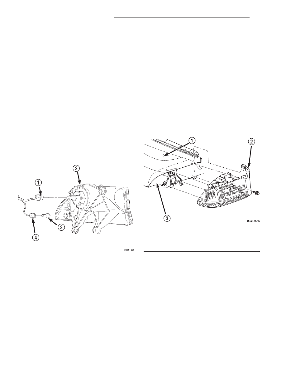
(3) Remove the retaining ring holding bulb to

headlamp.

(4) Pull bulb socket from headlamp (Fig. 10).
(5) Grasp bulb and pull from socket.

INSTALLATION

CAUTION: Do not touch the bulb glass with fingers
or other oily surfaces. Reduced bulb life will result.

(1) Position bulb into socket and push into place.
(2) Position bulb socket in headlamp.
(3) Install retaining ring holding bulb to head-

lamp.

(4) Install headlamp assembly.

(5) Connect the battery negative cable.

HEADLAMP UNIT

REMOVAL

(1) Disconnect and isolate the battery negative

cable.

(2) Remove the bolts attaching headlamp to the

inner fender panel (Fig. 11).

(3) Grasp the headlamp and firmly pull the head-

lamp to disengage it from the panel.

(4) Disengage the connector from the headlamp

bulb.

(5) Separate bulb from headlamp.
(6) Remove the bulb sockets from the front park/

turn signal/side marker lamps.

(7) Separate headlamp module from vehicle.

INSTALLATION

CAUTION: Do not touch the bulb glass with fingers
or other oily surfaces. Reduced bulb life will result.

(1) Install bulb sockets for the front park/turn sig-

nal/side marker lamps.

(2) Engage the connector to the headlamp bulb.
(3) Position headlamp in inner fender panel and

firmly push headlamp inward to lock into place.

(4) Install the bolts attaching headlamp to the

panel.

(5) Connect the battery negative cable.

Fig. 10 Headlamp Bulb

1 - HEADLAMP BULB SOCKET
2 - HEADLAMP
3 - BULB
4 - SIDE MARKER LAMP BULB SOCKET

Fig. 11 Headlamp

1 - FENDER
2 - SEAL
3 - INNER FENDER

8L - 16

LAMPS/LIGHTING - EXTERIOR

AN

HEADLAMP SWITCH (Continued)

ADJUSTMENTS

HEADLAMP ALIGNMENT

Headlamps can be aligned using the screen method

provided. Alignment Tool C-4466–A or equivalent can
also be used. Refer to the instructions provided with
the tool for proper procedures.

VEHICLE PREPARATION FOR HEADLAMP
ALIGNMENT

(1) Verify headlamp dimmer switch and high beam

indicator operation.

(2) Correct defective components that could hinder

proper headlamp alignment.

(3) Verify proper tire inflation.
(4) Clean headlamp lenses.
(5) Verify that luggage area is not heavily loaded.
(6) Fuel tank should be FULL. Add 2.94 kg (6.5

lbs.) of weight over the fuel tank for each estimated
gallon of missing fuel.

LAMP ALIGNMENT SCREEN PREPARATION

(1) Position vehicle on a level surface perpendicu-

lar to a flat wall 7.62 meters (25 ft) away from front
of headlamp lens (Fig. 12).

(2) If necessary, tape a line on the floor 7.62

meters (25 ft) away from and parallel to the wall.

(3) Measure from the floor up 1.27 meters (5 ft)

and tape a line on the wall at the centerline of the
vehicle. Sight along the centerline of the vehicle
(from rear of vehicle forward) to verify accuracy of
the line placement.

(4) Rock vehicle side-to-side three times to allow

suspension to stabilize.

(5) Jounce front suspension three times by pushing

downward on front bumper and releasing.

(6) Measure the distance from the center of head-

lamp lens to the floor. Transfer measurement to the
alignment screen (with tape). Use this line for
up/down adjustment reference.

(7) Measure distance from the centerline of the

vehicle to the center of each headlamp being aligned.
Transfer measurements to screen (with tape) to each
side of vehicle centerline. Use these lines for left/
right adjustment reference.

Fig. 12 Headlamp Alignment Screen—Typical

1 - CENTER OF VEHICLE
2 - CENTER OF HEADLAMP

3 - 7.62 METERS (25 FT.)
4 - FRONT OF HEADLAMP

AN

LAMPS/LIGHTING - EXTERIOR

8L - 17

HEADLAMP UNIT (Continued)

HEADLAMP ALIGNMENT

A properly aimed low beam headlamp will project a

high intensity light pattern on the screen with the
horizontal cut-off line aligned with the tape line 130
mm. (5.12 in.) below the headlamp centerline. The
intersection of the horizontal and 15 degree cut-off
lines in the projected pattern should align to the
intersection of the headlamp centerline vertical tape
line and the tape line 130 mm. (5.12 in.) below the
headlamp horizontal centerline. The high beam pat-
tern should be correct when the low beams are
aligned properly.

To adjust low beam headlamp, rotate alignment

screws (Fig. 13) to achieve the specified aim.

LICENSE PLATE LAMP

REMOVAL

(1) Disconnect and isolate the battery negative

cable.

(2) From the underside of the bumper, grasp the

bulb socket and rotate counter clockwise.

(3) Pull bulb socket from lamp.
(4) Grasp bulb and pull from socket.

INSTALLATION

(1) Position bulb in socket and press into place.
(2) Position bulb socket in lamp and rotate clock-

wise to lock into place.

(3) Connect the battery negative cable.

LICENSE PLATE LAMP UNIT

REMOVAL

(1) Disconnect and isolate the battery negative

cable.

(2) Remove license plate lamp bulb socket.
(3) From the underside of the bumper and using a

small flat blade, push in retaining tab to release the
lamp from the bumper.

(4) Separate lamp from bumper.

INSTALLATION

(1) Position lamp in bumper and press into place.
(2) Install license plate lamp bulb socket.
(3) Connect the battery negative cable.

MULTI-FUNCTION SWITCH

DESCRIPTION

The multi-function switch is secured with two

screws to the multi-function switch mounting hous-
ing on the left side of the steering column, just below
the steering wheel (Fig. 14). The only visible parts of
the multi-function switch are the control stalk that
extends through a dedicated opening in the left side
of the upper steering column shrouds, and the haz-
ard warning switch push button that protrudes
through an opening in the upper steering column
shroud on the top of the steering column. The
remainder of the switch, its mounting provisions, and
its electrical connections are all concealed beneath

Fig. 13 Headlamp Adjustment Screws

1 - HEADLAMP
2 - UP/DOWN ADJUSTMENT
3 - LEFT/RIGHT ADJUSTMENT
4 - PARK LAMP

Fig. 14 Multi-Function Switch

1 - MULTI-FUNCTION SWITCH
2 - HAZARD WARNING BUTTON
3 - TURN SIGNAL CANCEL ACTUATOR
4 - CONTROL STALK
5 - CONTROL KNOB

8L - 18

LAMPS/LIGHTING - EXTERIOR

AN

HEADLAMP UNIT (Continued)

the steering column shrouds. The multi-function
switch control stalk has both nomenclature and
International Control and Display Symbol graphics
applied to it, which identify its many functions. An
International Control and Display Symbol icon for
“Hazard Warning” is applied to the top of the hazard
warning switch push button.

The switch housing and its controls are constructed

of molded black plastic. A single connector receptacle
connects the switch to the vehicle electrical system
through a take out and connector of the instrument
panel wire harness.

The multi-function switch supports the following

functions and features:

• Continuous Wipe Modes - The control knob of

the multi-function switch provides two continuous
wipe switch positions, low speed or high speed.

• Hazard Warning Control - The internal cir-

cuitry and hardware of the multi-function switch pro-
vide detent switching for activation and deactivation
of the hazard warning system.

• Headlamp Beam Selection - The internal cir-

cuitry and hardware of the multi-function switch pro-
vide detent switching for selection of the headlamp
high or low beams.

• Headlamp Optical Horn - The internal cir-

cuitry and hardware of the multi-function switch
includes momentary switching of the headlamp high
beam circuits to provide an optical horn feature
(sometimes referred to as flash-to-pass), which allows
the vehicle operator to momentarily flash the head-
lamp high beams as an optical signalling device.

• Intermittent Wipe Mode - The control knob of

the multi-function switch provides an intermittent
wipe mode with multiple delay interval positions.

• Turn Signal Control - The internal circuitry

and hardware of the multi-function switch provide
both momentary non-detent switching and detent
switching with automatic cancellation for both the
left and right turn signals.

• Washer Mode - The control knob of the multi-

function switch provides washer system operation
when the knob is depressed towards the steering col-
umn.

The multi-function switch cannot be adjusted or

repaired. If any function of the switch is faulty, or if
the switch is damaged, the entire switch unit must
be replaced.

OPERATION

The

multi-function

switch

uses

conventionally

switched outputs and a variable resistor to control
the many functions and features it provides using
hard wired circuitry. The switch is grounded at all
times through a single wire take out with an eyelet
terminal connector of the instrument panel wire har-

ness that is secured by a nut to a ground stud
located on the left cowl side inner panel, near the left
instrument panel end bracket. When the ignition
switch is in the Accessory or On positions, battery
current from a fuse in the Junction Block (JB) is pro-
vided through a fused ignition switch output (run-
acc) circuit. Following are descriptions of how the
multi-function switch operates to control the many
functions and features it provides:

• Continuous Wipe Modes - When the control

knob of the multi-function switch is rotated to the
High or Low positions, the circuitry within the
switch provides a battery current output directly to
the high or low speed brush of the wiper motor.
When the control knob is in the Off position, the cir-
cuitry within the switch connects the output of the
wiper motor park switch to the low speed brush of
the wiper motor.

• Hazard Warning Control - The hazard warn-

ing push button is pushed down to unlatch the
switch and activate the hazard warning system, and
pushed down again to latch the switch and turn the
system off. When the hazard warning switch is
latched (hazard warning off), the push button will be
in a lowered position on the top of the steering col-
umn shroud; and, when the hazard warning switch is
unlatched (hazard warning on), the push button will
be in a raised position. The multi-function switch
hazard warning circuitry provides a signal to the
hazard warning sense of the combination flasher to
activate or deactivate the flasher output to the haz-
ard warning lamps.

• Headlamp Beam Selection - The multi-func-

tion switch control stalk is pulled towards the steer-
ing wheel past a detent, then released to actuate the
headlamp beam selection switch. Each time the con-
trol stalk is actuated in this manner, the opposite
headlamp mode from what is currently selected will
be activated. The internal circuitry of the headlamp
beam selection switch directs a ground signal output
from the headlamp switch to the appropriate low
beam or high beam sense of the Central Timer Mod-
ule (CTM). The CTM then controls a hard wired out-
put to activate the selected headlamp beams.

• Headlamp Optical Horn - The left multi-func-

tion switch control stalk is pulled towards the steer-
ing wheel to just before a detent, to momentarily
activate the headlamp high beams. The high beams
will remain illuminated until the control stalk is
released. The internal circuitry of the headlamp
beam selection switch provides a momentary ground
path to the CTM high beam sense.

• Intermittent Wipe Mode - When the multi-

function switch control knob is rotated to the Delay
position, the circuitry within the switch provides a
battery current signal to the Central Timer Module

AN

LAMPS/LIGHTING - EXTERIOR

8L - 19

MULTI-FUNCTION SWITCH (Continued)


Content   ..  330  331  332  333   ..