Dodge Dakota (R1). Manual - part 277
INSTALLATION
(1) Install fan blade assembly to viscous fan drive.
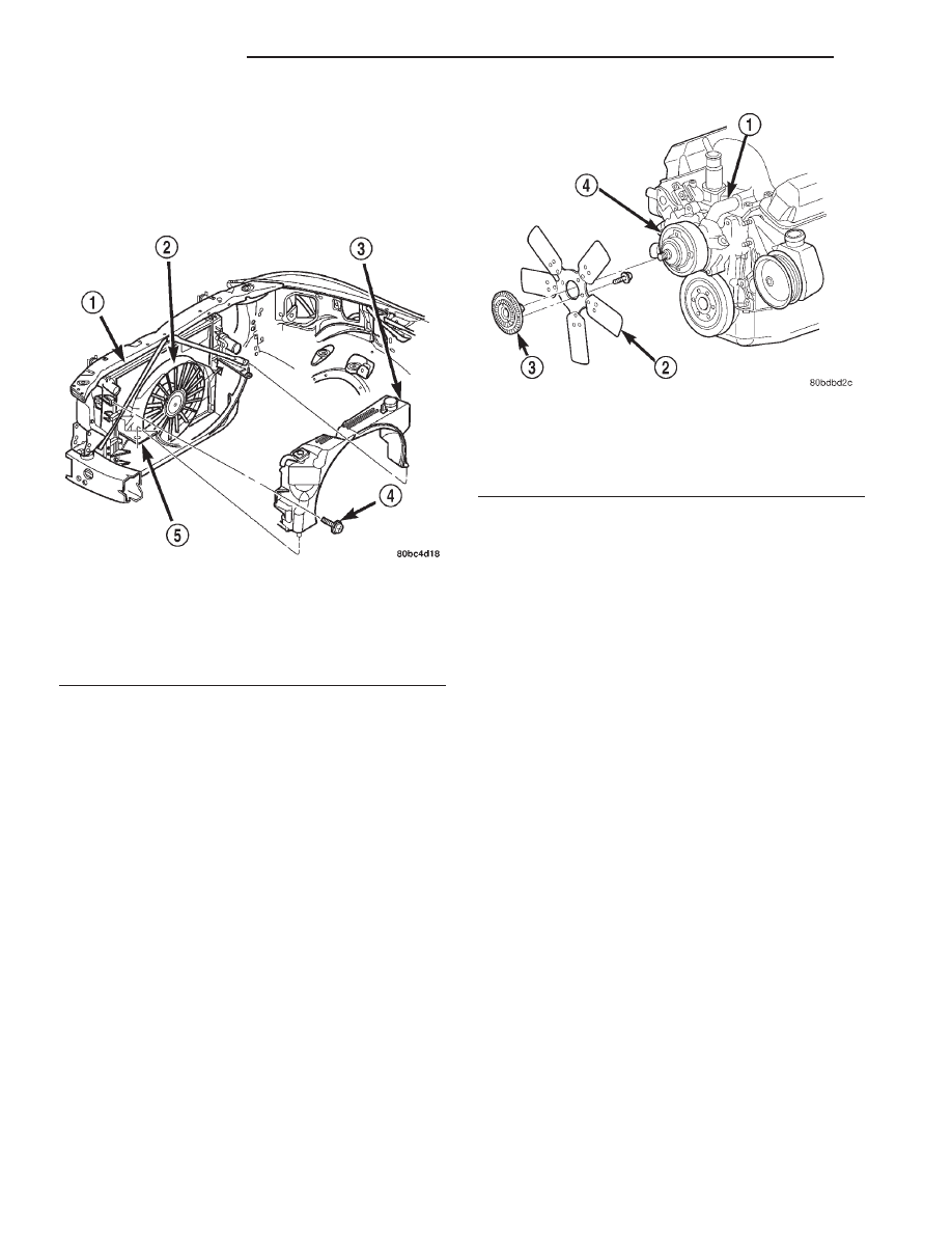
Tighten bolts (Fig. 34) to 23 N·m (17 ft. lbs.) torque.
(2) Position fan blade/viscous fan drive assembly
and upper shroud into vehicle.
(3) Install fan shroud retaining screws (Fig. 35).
(4) Install fan blade/viscous fan drive assembly to
water pump shaft (Fig. 33).
(5) Connect battery negative cable.
WATER PUMP
DESCRIPTION
The water pump is located on the engine front
cover, and has an integral pulley attached (Fig. 36).
The water pump impeller is pressed onto the rear
of a shaft that rotates in a bearing pressed into the
water pump body. The body has a small hole for ven-
tilation. The water pump seals are lubricated by
antifreeze in the coolant mixture. Additional lubrica-
tion is not necessary.
OPERATION
A
centrifugal
water
pump
circulates
coolant
through the water jackets, passages, intake manifold,
radiator core, cooling system hoses and heater core,
this coolant absorbs the heat generated when the
engine is running. The pump is driven by the engine
crankshaft via a drive belt.
REMOVAL
The water pump can be removed and installed
without discharging the air conditioning system (if
equipped).
(1) Disconnect battery negative cable.
(2) Drain cooling system (Refer to 7 - COOLING/
ENGINE - STANDARD PROCEDURE).
(3) Do not waste reusable coolant. If solution is
clean, drain coolant into a clean container for reuse.
WARNING: CONSTANT TENSION HOSE CLAMPS
ARE USED ON MOST COOLING SYSTEM HOSES.
WHEN REMOVING OR INSTALLING, USE ONLY
TOOLS DESIGNED FOR SERVICING THIS TYPE OF
CLAMP, SUCH AS SPECIAL CLAMP TOOL (NUMBER
6094) (Fig. 42). SNAP-ON CLAMP TOOL (NUMBER
HPC-20) MAY BE USED FOR LARGER CLAMPS.
ALWAYS WEAR SAFETY GLASSES WHEN SERVIC-
ING CONSTANT TENSION CLAMPS.
CAUTION: A number or letter is stamped into the
tongue of constant tension clamps (Fig. 43). If
replacement is necessary, use only an original
equipment clamp with matching number or letter.
(4) Remove upper radiator hose clamp and hose at
radiator.
(5) The thermal viscous fan drive is attached
(threaded) to the water pump hub shaft (Fig. 38).
Remove fan/viscous fan drive assembly from water
pump by turning mounting nut counterclockwise as
viewed from front. Threads on viscous fan drive are
RIGHT HAND. A Snap-On 36 MM Fan Wrench
(number SP346 from Snap-On Cummins Diesel Tool
Fig. 35 Upper Fan Shroud Removal/Installation
1 - RADIATOR
2 - ELECTRIC COOLING FAN
3 - UPPER SHROUD & WASHER RESERVOIR UNIT
4 - SCREW
5 - LOWER SHROUD
Fig. 36 Water Pump Location - Typical
1 - WATER PUMP BYPASS HOSE
2 - FAN BLADE ASSEMBLY
3 - VISCOUS FAN DRIVE
4 - WATER PUMP AND PULLEY
7a - 54
5.2L ENGINE
R1
VISCOUS FAN DRIVE (Continued)