Dodge Dakota (ND). Manual - part 313
 

  Index      Dodge     Dodge Dakota (ND) 2005 - service repair manual 2005 year


Search            


Content   ..  311  312  313  314   ..


Dodge Dakota (ND). Manual - part 313


NOTE: If the brake indicator stays on with the ignition switch in the On position and the park brake
released, or comes on while driving, the brake system must be diagnosed and repaired prior to performing
the following tests. (Refer to 5 - BRAKES - DIAGNOSIS AND TESTING). If no brake system problem is found,
the following procedures will help to locate a shorted or open park brake switch sense circuit, or a faulty
park brake switch.

INDICATOR ILLUMINATES DURING BULB TEST, BUT DOES NOT WHEN PARK BRAKE APPLIED

1. Disconnect and isolate the battery negative cable. Disconnect the body wire harness connector for the park

brake switch from the switch terminal. Apply the parking brake. Check for continuity between the park brake
switch terminal and a good ground. There should be continuity. If OK, go to Step 2. If not OK, replace the faulty
park brake switch.

2. Disconnect the instrument panel wire harness connector (Connector C1) for the instrument cluster from the clus-

ter connector receptacle. Check for continuity between the park brake switch sense circuit cavities of the body
wire harness connector for the park brake switch and the instrument panel wire harness connector for the instru-
ment cluster. There should be continuity. If not OK, repair the open park brake switch sense circuit between the
park brake switch and the instrument cluster as required.

INDICATOR REMAINS ILLUMINATED - BRAKE SYSTEM CHECKS OK

1. Disconnect and isolate the battery negative cable. Disconnect the body wire harness connector for the park

brake switch from the switch terminal. Check for continuity between the terminal of the park brake switch and a
good ground. There should be no continuity with the park brake released, and continuity with the park brake
applied. If OK, go to Step 2. If not OK, replace the faulty park brake switch.

2. Disconnect the instrument panel wire harness connector (Connector C1) for the instrument cluster from the clus-

ter connector receptacle. Check for continuity between the park brake switch sense circuit cavity of the body wire
harness connector for the park brake switch and a good ground. There should be no continuity. If not OK, repair
the shorted park brake switch sense circuit between the park brake switch and the instrument cluster as
required.

REMOVAL

WARNING: To avoid personal injury or death, on vehicles equipped with airbags, disable the supplemental
restraint system before attempting any steering wheel, steering column, airbag, occupant classification sys-
tem, seat belt tensioner, impact sensor, or instrument panel component diagnosis or service. Disconnect
and isolate the battery negative (ground) cable, then wait two minutes for the system capacitor to discharge
before performing further diagnosis or service. This is the only sure way to disable the supplemental
restraint system. Failure to take the proper precautions could result in accidental airbag deployment.

1. Disconnect and isolate the battery negative cable.

2. Apply the parking brake.

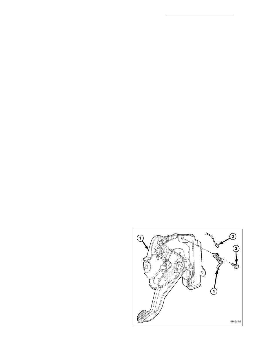
3. Reach under the left end of the instrument panel to

access and disconnect the body wire harness con-
nector (2) from the terminal of the park brake
switch (4) located on the park brake lever mecha-
nism (1) on the left cowl side inner panel.

4. Remove the screw (3) that secures the park brake

switch to the park brake lever mechanism.

5. Remove the switch from the park brake lever

mechanism.

8L - 114

LAMPS/LIGHTING - EXTERIOR - SERVICE INFORMATION

ND

INSTALLATION

WARNING: To avoid personal injury or death, on vehicles equipped with airbags, disable the supplemental
restraint system before attempting any steering wheel, steering column, airbag, occupant classification sys-
tem, seat belt tensioner, impact sensor, or instrument panel component diagnosis or service. Disconnect
and isolate the battery negative (ground) cable, then wait two minutes for the system capacitor to discharge
before performing further diagnosis or service. This is the only sure way to disable the supplemental
restraint system. Failure to take the proper precautions could result in accidental airbag deployment.

1. Reach under the left end of the instrument panel to

position park brake switch (4) onto the park brake
lever mechanism (1) on the left cowl side inner
panel. Be certain to engage the locating pin on the
back of the switch insulator into the locating slot in
the lever mechanism bracket.

2. Install and tighten the screw (3) that secures the

park brake switch to the park brake lever mecha-
nism. Tighten the screw to 3 N·m (24 in. lbs.).

3. Reconnect the body wire harness connector (2) to

the terminal of the park brake switch.

4. Reconnect the battery negative cable.

5. Turn the ignition switch to the On position and

check for proper brake indicator operation with the
parking brake applied, then release the parking
brake

and

check

that

the

brake

indicator

extinguishes.

RELAY-PARK LAMP

DESCRIPTION

The park lamp relay is a conventional International
Standards Organization (ISO) micro relay. Relays con-
forming to the ISO specifications have common phys-
ical dimensions, current capacities, terminal patterns,
and terminal functions. This relay is contained within a
small, rectangular, molded plastic housing and is con-
nected to all of the required inputs and outputs
through five integral male spade-type terminals that
extend from the relay base plate.

The park lamp relay is located in the Power Distribu-
tion Center (PDC) in the engine compartment near the
battery. Refer to the layout label on the underside of
the PDC cover for specific relay cavity assignment
information. The park lamp relay cannot be adjusted
or repaired and, if faulty or damaged, the unit must be
replaced.

OPERATION

The park lamp relay is an electromechanical switch that uses a low current input from the Front Control Module
(FCM) (also referred to as the Integrated Power Module/IPM) to control a high current output to the park lamps.
Within the relay are an electromagnetic coil, a movable contact and two fixed contact points. A resistor is connected

ND

LAMPS/LIGHTING - EXTERIOR - SERVICE INFORMATION

8L - 115

in parallel with the coil, and helps to dissipate voltage spikes and electromagnetic interference that can be gener-
ated as the field of the relay coil collapses.

The movable common supply contact point is held against the fixed normally closed contact point by spring pres-
sure. When the relay coil is energized, an electromagnetic field is produced by the coil windings. This field draws
the movable contact away from the normally closed contact, and holds it against the normally open contact. When
the relay coil is de-energized, spring pressure returns the movable contact back against the normally closed contact.

The inputs and outputs of the park lamp relay include:

Common Supply Terminal (30) - The common feed terminal is connected to a fused B(+) circuit at all times.

Coil Ground Terminal (85) - The coil ground terminal is connected to a fused B(+) circuit at all times.

Coil Battery Terminal (86) - The coil battery terminal is connected to a control output of the FCM through a
park lamp relay control circuit. The FCM controls park lamp operation by controlling a ground path through this
circuit.

Normally Open Terminal (87) - The normally open terminal is connected to the park lamps through a park
lamp relay output circuit and provides battery voltage to the park lamps whenever the relay is energized.

Normally Closed Terminal (87A) - The normally closed terminal is not connected to any circuit in this appli-
cation, but will have battery voltage present whenever the relay is de-energized.

The park lamp relay can be diagnosed using conventional diagnostic tools and methods. Refer to the appropriate
wiring information.

REAR LAMP UNIT

REMOVAL

BULB

NOTE: The rear lamp unit contains two bulbs:
park/turn signal/side marker and backup. The ser-
vice procedures for each bulb are the same, only
the bulb sizes and types may differ.

1. Disconnect and isolate the battery negative cable.

2. Remove the rear lamp unit (1) from the end of the

quarter panel. (Refer to 8 - ELECTRICAL/LAMPS/
LIGHTING

-

EXTERIOR/REAR

LAMP

-

REMOVAL).

3. Disconnect the wire harness connector (4) from the

park/turn signal/side marker (2) or the backup (3)
bulb socket on the back of the lamp housing.

4. Firmly grasp the socket on the back of the housing

and rotate it counterclockwise about 30 degrees to
unlock it.

5. Pull the socket and bulb straight out from the

keyed opening in the housing.

6. Pull the base of the bulb straight out of the socket.

8L - 116

LAMPS/LIGHTING - EXTERIOR - SERVICE INFORMATION

ND

LAMP

1. Disconnect and isolate the battery negative cable.

2. Lower the tailgate to access and remove the two

screws (4) that secure the rear lamp unit (5) to the
side jamb (3) of the tailgate opening.

3. Pull the outboard side of the rear lamp unit rear-

ward far enough to unsnap the two ball studs on
the outboard side of the lamp housing from the two
round grommets (2) in the outer box side panel.

4. Pull the lamp away from the vehicle far enough to

access and disconnect the two wire harness con-
nectors from the two bulb sockets on the back of
the lamp housing.

5. Remove the lamp from the lamp opening of the

outer box side panel.

INSTALLATION

BULB

CAUTION: Always use the correct bulb size and type for replacement. An incorrect bulb size or type may
overheat and cause damage to the lamp, the socket and/or the lamp wiring.

NOTE: The rear lamp unit contains two bulbs:
park/turn signal/side marker and backup. The ser-
vice procedures for each bulb are the same, only
the bulb sizes and types may differ.

1. Align the base of the bulb with the park/turn signal/

side marker (2) or the backup (3) bulb socket.

2. Push the bulb straight into the socket until the base

is firmly seated.

3. Align the socket and bulb with the keyed opening

on the back of the rear lamp unit housing (1).

4. Insert the socket and bulb into the housing until the

socket is firmly seated.

5. Rotate the socket clockwise about 30 degrees to

lock it into place.

6. Reconnect the wire harness connector (4) to the

socket.

7. Reinstall the rear lamp unit onto the end of the quarter panel. (Refer to 8 - ELECTRICAL/LAMPS/LIGHTING -

EXTERIOR/REAR LAMP - INSTALLATION).

8. Reconnect the battery negative cable.

ND

LAMPS/LIGHTING - EXTERIOR - SERVICE INFORMATION

8L - 117


Content   ..  311  312  313  314   ..