Dodge Dakota (ND). Manual - part 215
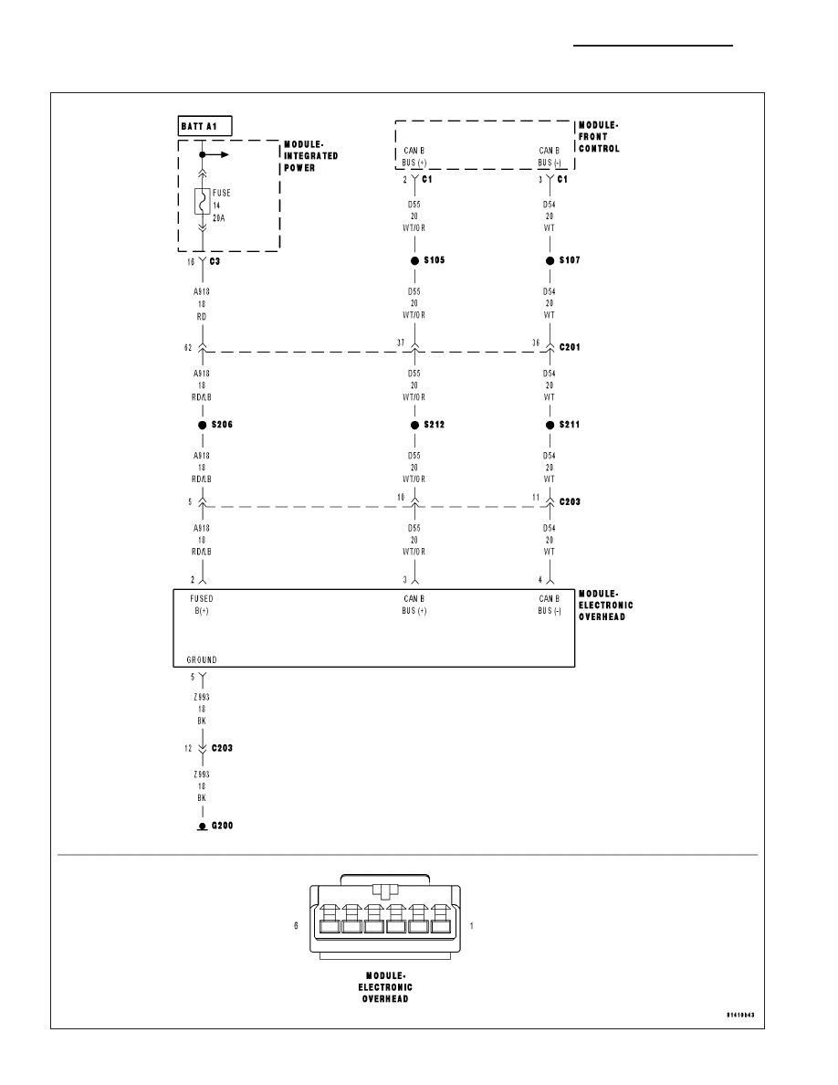
*NO RESPONSE FROM EOM (ELECTRONIC OVERHEAD MODULE)
8E - 116
ELECTRONIC CONTROL MODULES - ELECTRICAL DIAGNOSTICS
ND
|
|
|
*NO RESPONSE FROM EOM (ELECTRONIC OVERHEAD MODULE) 8E - 116 ELECTRONIC CONTROL MODULES - ELECTRICAL DIAGNOSTICS ND |