Dodge Dakota (ND). Manual - part 21


  Index      Dodge     Dodge Dakota (ND) 2005 - service repair manual 2005 year


Search            


Content   ..  19  20  21  22   ..


Dodge Dakota (ND). Manual - part 21


INSTALLATION

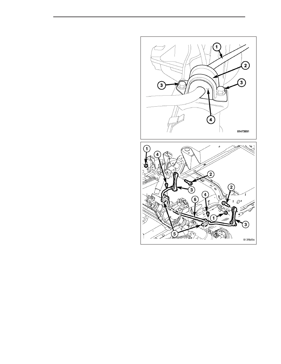
1. Install the stabilizer bushings (4).

2. Install the stabilizer bar (1) and center it with equal

spacing on both sides. Install stabilizer bar retain-
ers (2) and tighten bolts (3) to 54 N·m (40 ft. lbs.).

3. Install link (3) into the stabilizer bar (6). Install

mounting nuts and bolts. Tighten stabilizer link nuts
to 54 N·m (40 ft. lbs.).

4. Remove support and lower vehicle.

2 - 52

REAR

ND

DIFFERENTIAL & DRIVELINE

TABLE OF CONTENTS

page

page

PROPELLER SHAFT

. . . . . . . . . . . . . . . . . . . . . . 1

HALF SHAFT

. . . . . . . . . . . . . . . . . . . . . . . . . . . 21

FRONT AXLE - C205F

. . . . . . . . . . . . . . . . . . . . . 32

REAR AXLE - 8 1/4

. . . . . . . . . . . . . . . . . . . . . . . 71

REAR AXLE - 9 1/4

. . . . . . . . . . . . . . . . . . . . . . 109

PROPELLER SHAFT

TABLE OF CONTENTS

page

page

PROPELLER SHAFT

DIAGNOSIS AND TESTING

PROPELLER SHAFT

. . . . . . . . . . . . . . . . . . . . 1

STANDARD PROCEDURE

PROPELLER SHAFT ANGLE

. . . . . . . . . . . . . . 4

SPECIFICATIONS

. . . . . . . . . . . . . . . . . . . . . . . . 6

SPECIAL TOOLS

. . . . . . . . . . . . . . . . . . . . . . . . 7

SHAFT-PROPELLER FRONT

REMOVAL

. . . . . . . . . . . . . . . . . . . . . . . . . . . . . . 8

INSTALLATION

. . . . . . . . . . . . . . . . . . . . . . . . . . 9

SHAFT-PROPELLER REAR

REMOVAL

. . . . . . . . . . . . . . . . . . . . . . . . . . . . . 10

INSTALLATION

. . . . . . . . . . . . . . . . . . . . . . . . . 11

UNIVERSAL JOINTS-SINGLE CARDAN

DISASSEMBLY

DISASSEMBLY - WITH SNAP RINGS

. . . . . . . 11

DISASSEMBLY - WITH INJECTED RINGS

. . . 13

ASSEMBLY

ASSEMBLY - WITH SNAP RINGS

. . . . . . . . . 15

ASSEMBLY - WITH INJECTED RINGS

. . . . . . 16

PROPELLER SHAFT

DIAGNOSIS AND TESTING

PROPELLER SHAFT

PROPELLER SHAFT VIBRATION

Out-of-round tires or wheels that are out of balance, will cause a low frequency vibration.

Driveline vibration can also caused by loose or damaged engine mounts.

Propeller shaft vibration increases with vehicle speed. A vibration that occurs at a specific speed range, is not usu-
ally caused by an out of balance propeller shaft. Defective universal joints or an incorrect propeller shaft angle are
usually the cause of such a vibration.

ND

DIFFERENTIAL & DRIVELINE

3 - 1

DRIVELINE VIBRATION

Drive Condition

Possible Cause

Correction

Propeller Shaft Noise

1) Undercoating or other foreign
material on shaft.

1) Clean exterior of shaft and wash
with solvent.

2) Loose U-joint clamp screws.

2) Install new clamps and screws
and tighten to proper torque.

3) Loose or bent U-joint yoke or
excessive runout.

3) Install new yoke.

4) Incorrect driveline angularity.

4) Measure and correct driveline
angles.

5) Rear spring center bolt not in
seat.

5) Loosen spring u-bolts and seat
center bolt.

6) Worn U-joint bearings.

6) Install new U-joint.

7) Propeller shaft damaged or out
of balance.

7) Installl new propeller shaft.

8) Broken rear spring.

8) Install new rear spring.

9) Excessive runout or unbalanced
condition.

9) Re-index propeller shaft, test,
and evaluate.

10) Excessive drive pinion gear
shaft runout.

10) Re-index propeller shaft and
evaluate.

11) Excessive axle yoke deflection.

11) Inspect and replace yoke if
necessary.

12) Excessive transfer case runout.

12) Inspect and repair as necessary.

Universal Joint Noise

1) Loose U-joint clamp screws.

1) Install new clamps and screws
and tighten to proper torque.

2) Lack of lubrication.

2) Replace as U-joints as
necessary.

PROPELLER SHAFT BALANCE

If propeller shaft is suspected of being out of balance,
use the following procedure.

NOTE: Indexing propeller shaft 180° relative to the
yoke may eliminate some vibrations.

1. Raise and support vehicle.

2. Clean all foreign material from the propeller shaft

and universal joints.

3. Inspect propeller shaft for missing balance weights,

broken welds and bent areas. If propeller shaft is
bent, it must be replaced.

4. Inspect universal joints for wear and properly

installed.

5. Check propeller shaft bolt torques.

6. Remove wheels and install lug nuts to retain brake

rotors.

7. Mark and number the shaft six inches from the pin-

ion yoke end at four positions 90° apart.

8. Run and accelerate vehicle until vibration occurs. Note the intensity and speed the vibration occurred. Stop the

engine.

3 - 2

PROPELLER SHAFT

ND

9. Install a screw clamp at position (1).

10. Start engine and check vibration. If there is little

or no change move the clamp to the next posi-
tions. Repeat the vibration test.

NOTE: If there is no difference in vibration at this
positions, the vibration may not be the propeller
shaft.

11. If vibration decreased, install a second clamp (1)

and repeat the test.

12. If additional clamp causes an additional vibration,

separate the clamps 1/2 inch (1) above and below
the mark. Repeat the vibration test.

13. Increase distance between the clamp screws (1)

(2) and repeat test, until the least amount of vibra-
tion is noticed. Bend the slack end of the clamps
so screws will not loosen.

14. If vibration remains unacceptable, repeat the pro-

cedure to the front end of the propeller shaft.

15. Install wheels and lower vehicle.

PROPELLER SHAFT RUNOUT

1. Clean propeller shaft surface, where dial indicator will contact the shaft.

2. Install dial indicator perpendicular to the shaft surface.

3. Measure runout at the center and ends of the shaft away from weld areas, so weld process does not affect

measurements.

4. Refer to Runout Specifications chart.

5. If runout is out of specification, index the shaft 180° and take shaft runout measurements again.

6. If runout is now within specifications, mark shaft and yokes for proper orientation.

7. If runout is not within specifications, verify runout of the transmission/transfer case and axle are within specifi-

cations. Correct as necessary and measure propeller shaft runout again.

8. Replace propeller shaft if the runout still exceeds the limits.

ND

PROPELLER SHAFT

3 - 3


Content   ..  19  20  21  22   ..