Chrysler Le Baron, Dodge Dynasty, Plymouth Acclaim. Manual - part 328
(3) Remove both upper and lower steering column
shrouds.
(4) Remove multi-function switch tamper proof
mounting screws (Fig.7).
(5) Gently pull switch away from column. Loosen
connector screw. The screw will remain in the con-
nector.
(6) Remove wiring connector from multi-function
switch.
INSTALLATION
(1) Install wiring connector to switch and tighten
connector retaining screw to 2 N
Im (17 in. lbs.)
torque.
(2) Mount multi-function switch to column and
tighten retaining screws to 2 N
Im (17 in. lbs.) torque.
(3) Install steering column covers. Tighten retain-
ing screws to 2 N
I (17 in. lbs.) torque.
(4) Tilt column only install tilt lever.
(5) Install negative battery cable.
(6) Check all functions of switch for proper opera-
tion.
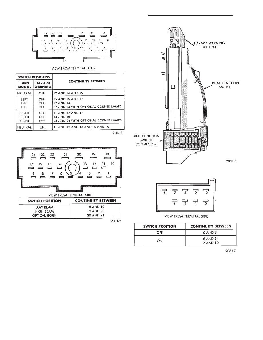
Fig. 2 Turn Signal and Hazard Switch Continuity
Fig. 3 Beam Select Switch Continuity
Fig. 4 Dual-Function Switch Connector
Fig. 5 Hazard Warning Switch Continuity—AJ Body
8J - 4
TURN SIGNALS AND HAZARD WARNING FLASHER
Ä