Chrysler Le Baron, Dodge Dynasty, Plymouth Acclaim. Manual - part 231
pared by the (CAB) and used to detect brake system
faults that would require Anti -Lock Braking to be
disabled.
The Boost Pressure Transducer is mounted on the
bottom of the hydraulic assembly, (Fig. 1) and moni-
tors booster servo pressure. The Primary Pressure
Transducer is mounted on the left side of the hydrau-
lic assembly and monitors primary master cylinder
pressure.
DIFFERENTIAL PRESSURE SWITCH
A non-latching Differential Pressure Switch is used
to detect a pressure difference greater than 2,068
kPa (300 psi.) between the primary and secondary
master cylinder hydraulic circuits. If detected, the
Differential Pressure Switch grounds the output of
the primary pressure transducer (circuit B-218). This
results in a 0.0 volt signal from the Primary Pres-
sure Transducer that is sensed by the (CAB) as a dif-
ferential pressure fault. The (CAB) will then light
the Red Brake Warning Lamp and the Amber Anti-
Lock Warning Lamp and disable the Anti-Lock brak-
ing function. See Fig. 1 for location of the differential
pressure switch.
PROPORTIONING VALVES
The
ABS
system
uses
screw-in
Proportioning
Valves in place of the conventional Height Sensing
Proportioning Valve. Each rear brake circuit has its
own screw-in Proportioning Valve that is attached to
the rear brake outlet ports of the hydraulic assembly
(Fig. 1). These valves limit brake pressure to the
rear brakes after a certain brake pressure is reached.
This improves front to rear wheel brake balance dur-
ing normal braking.
FILTERS-SERVICEABILITY
There is a screen filter in each of the two master
cylinder fill ports. There is also a low pressure filter
for the pump/motor. The filter is integral to the
Pump/Motor low pressure hose.
FLUID LEVEL SWITCH
A Low Fluid Switch is located in the hydraulic as-
sembly fluid reservoir, (Fig. 1). The switch consists of
a float and magnetic reed switch that closes when
low fluid is detected. The Low Fluid Switch is used
as an input, to the Red Brake Warning Lamp, the
(CAB), and the EVIC (if so equipped). When a low
fluid condition exists the switch will close, grounding
the low fluid circuit and illuminating the Red Brake
Warning Lamp. The (CAB) will disable the Anti-
Lock Function and light the Amber Anti-Lock Warn-
ing Lamp if vehicle is in motion above 3 mph. If
vehicle is not in motion, the Amber Anti-Lock Warn-
ing Lamp will NOT be lit.
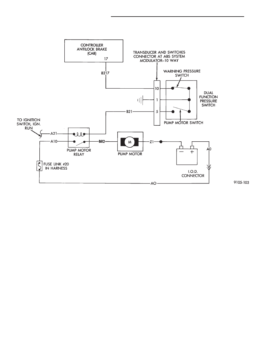
DUAL FUNCTION PRESSURE SWITCH WIRING DIAGRAM
5 - 78
ANTI-LOCK 10 BRAKE SYSTEM
Ä