Chrysler Le Baron, Dodge Dynasty, Plymouth Acclaim. Manual - part 218
HYDRAULIC SYSTEM CONTROL VALVES
INDEX
page
page
ABS Brake Proportioning Valve Operation
. . . . . . 27
General Information
. . . . . . . . . . . . . . . . . . . . . . . 26
Hydraulic System Service Procedures
. . . . . . . . . 27
Non-ABS Proportioning Unit Operation
. . . . . . . . 26
Pressure Differential Warning Light Switch
. . . . . . 26
Testing ABS Proportioning Valves
. . . . . . . . . . . . 29
GENERAL INFORMATION
Most models not equipped with an Anti-Lock brak-
ing system have a combination hydraulic system con-
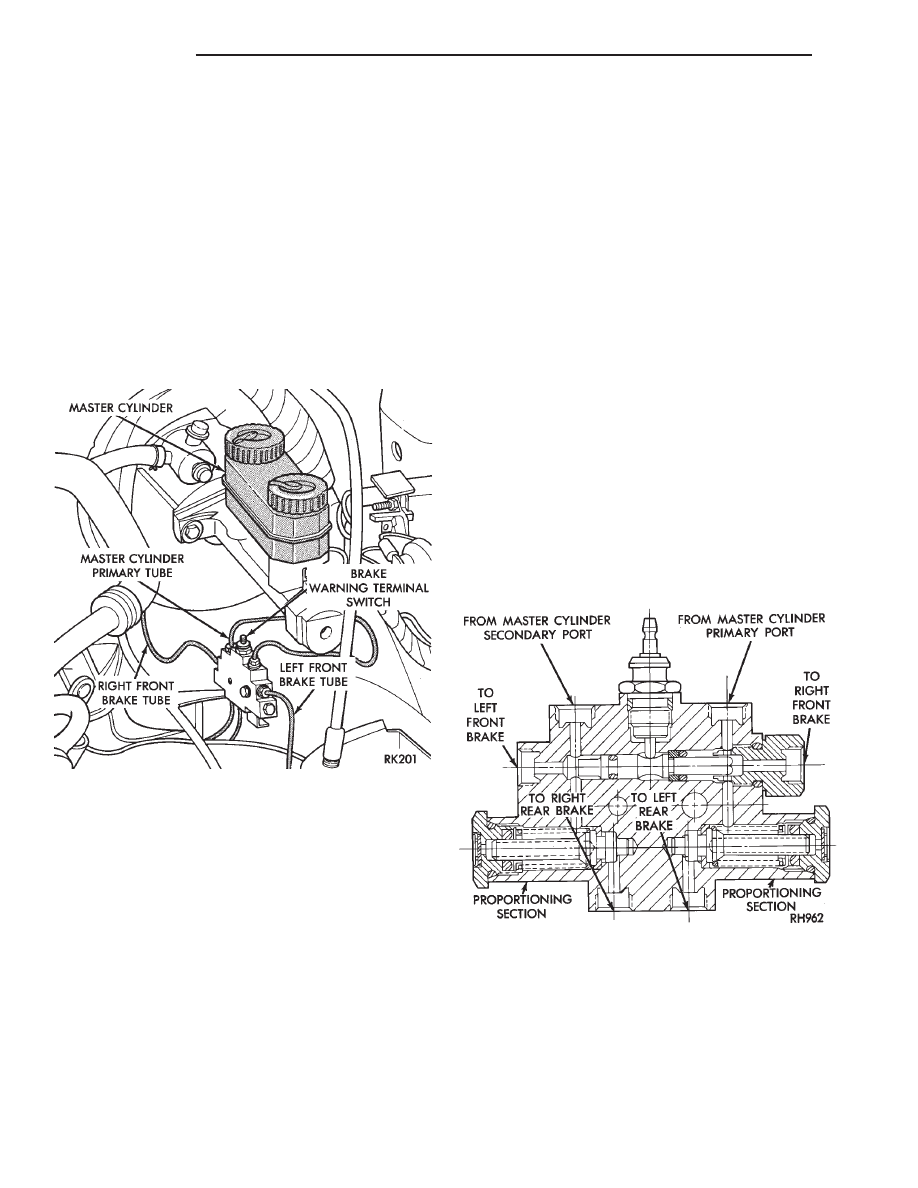
trol valve in the brake hydraulic system (Fig. 1). The
valve is attached to the frame rail below the master
cylinder.
The control valve assembly combines a warning
switch with a dual proportioning valve (Fig. 2)
Proportioning valves balance front to rear braking
by controlling at a given ratio, the increase in rear
system hydraulic pressure above a preset level. Un-
der light pedal application, the valve allows full hy-
draulic pressure to the rear brakes.
There is only one valve assembly in each vehicle,
see Valve Application Chart. During any service pro-
cedures identify valve assemblies by part number as
well as split point (PSI) and slope.
PRESSURE DIFFERENTIAL WARNING LIGHT
SWITCH
The hydraulic brake system, on non-ABS vehicles,
is split diagonally. The left front and right rear
brakes are part of one system. And the right front
and left rear are part of another. Both systems are
routed through, but hydraulically separated by a Pres-
sure Differential Switch. The function of the Pressure
Differential Switch is to alert the driver of a malfunc-
tion in the brake system.
If hydraulic pressure is lost in one system, the
warning light switch will activate a red light on the
instrument panel, when the brake pedal is depressed.
At this point the brakes require service. However, since
the brake systems are split diagonally the vehicle will
retain 50% of its stopping capability in the event of a
failure in either half.
The warning light switch is the latching type. It
will automatically center itself after the repair is
made and the brake pedal is depressed.
The instrument panel bulb can be checked each time
the ignition switch is turned to the start position or the
parking brake is set.
NON-ABS PROPORTIONING UNIT OPERATION
The proportioning valve section operates by trans-
mitting full input pressure to the rear brakes up to a
certain point. This is called the split point. Beyond this
point it reduces the amount of pressure increase to the
rear brakes according to a certain ratio.
On light pedal applications equal brake pressure will
be transmitted to the front and rear brakes. On heavier
pedal
applications
the
pressure
transmitted
Fig. 1 Brake Combination Valve And Warning
Switch Location
Fig. 2 Switch and Valve Assembly
5 - 26
BRAKES
Ä