Chrysler Le Baron, Dodge Dynasty, Plymouth Acclaim. Manual - part 210


  Index      Dodge     Chrysler Le Baron, Dodge Dynasty, Plymouth Acclaim - service repair manual 1993 year


Search            


Content   ..  208  209  210  211   ..


Chrysler Le Baron, Dodge Dynasty, Plymouth Acclaim. Manual - part 210


air entering the outer end of snorkel is 60°C (140°F.) or
higher, the door should be in the down (heat off)
position.

(4) Remove the air cleaner from the engine and

allow it to cool down to 46°C (115°F). With 20 inches of
vacuum applied to the sensor, the door should be in the
up (heat on position). If the door does not rise to the
heat on position, check the vacuum diaphragm for
proper operation.

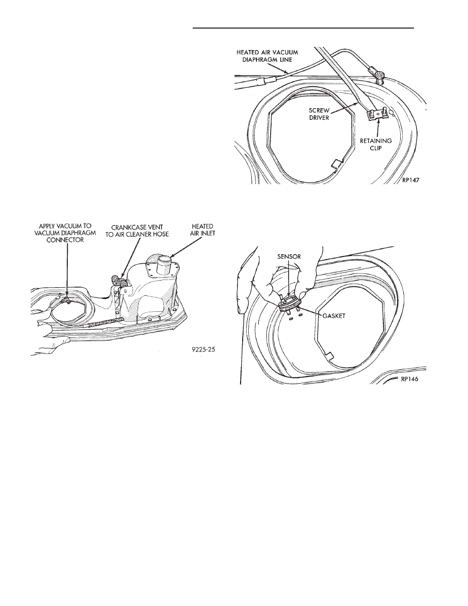
(5) To test the diaphragm, apply 20 inches of vacuum

to it with vacuum pump tool number C-4207 or equiva-
lent (Fig. 3). The diaphragm should not bleed down
more than 10 inches of vacuum in 5 minutes. The door
should not lift off the bottom of the snorkel at less than
2 inches of vacuum. The door should be in the full up
position with no more than 4 inches of vacuum.

(6) If the vacuum diaphragm does not perform ad-

equately, replace the heated air assembly.

(7) If the vacuum diaphragm performs adequately

but proper temperature is not maintained, replace the
sensor and repeat the temperature checks in steps 2
and 3.

HEATED AIR TEMPERATURE SENSOR SER-
VICE

REMOVAL

(1) Remove air cleaner housing from vehicle.
(2) Disconnect vacuum hoses from air temperature

sensor. Remove and discard retainer clips, new clips
are supplied with a new sensor (Fig. 4).

(3) Remove and discard sensor and gasket.

INSTALLATION

(1) Position gasket on the sensor. Install sensor (Fig.

5).

(2) While supporting the sensor on outer diameter,

install new retainer clips securely. Ensure the gasket
compresses to form an air seal. Do not attempt to
adjust the sensor.

HEATED OXYGEN SENSOR (O

2

SENSOR)

The O

2

sensor threads into the exhaust manifold. It

provides an input voltage to the powertrain control
module (PCM). The input tells the PCM the oxygen
content of the exhaust gas (Fig. 6, 7, 8, 9, or 10). The
PCM uses this information to fine tune the air-fuel
ratio by adjusting injector pulse width.

The O

2

sensor produces voltages from 0 to 1 volt,

depending upon the oxygen content of the exhaust gas
in the exhaust manifold. When a large amount of
oxygen is present (caused by a lean air-fuel mixture),
the sensor produces a low voltage. When there is a
lesser amount of oxygen present (rich air-fuel mixture),
the sensor produces a higher voltage. By monitoring
the oxygen content and converting it to electrical
voltage, the sensor acts as a rich-lean switch.

Fig. 3 Testing Vacuum Diaphragm on Heated Air In-

let Systems

Fig. 4 Removing Sensor Clips

Fig. 5 Air Temperature Sensor Installation

25 - 18

EMISSION CONTROL SYSTEMS

Ä

The oxygen sensor contains a heating element that

keeps it at proper temperature during all operating
modes. Maintaining correct sensor temperature at all

times allows the system to enter into closed loop op-
eration sooner and remain in closed loop during pe-
riods of extended idle.

In Closed Loop operation the powertrain control

module (PCM) monitors the O

2

sensor input (along

with other inputs) and adjusts the injector pulse
width accordingly. During Open Loop operation the
PCM ignores the O

2

sensor input. The PCM adjusts

injector pulse width based on preprogrammed (fixed)
oxygen sensor input values and the current inputs
from other sensors.

REMOVAL

CAUTION: Do not pull on the oxygen sensor wire
when disconnecting the electrical connector.

WARNING: THE EXHAUST MANIFOLD MAY BE EX-
TREMELY HOT. USE CARE WHEN SERVICING THE
OXYGEN SENSOR.

Fig. 6 Heated Oxygen Sensor—2.5L Engine

Fig. 7 Heated Oxygen Sensor—2.5L MPI Engine

(Flexible Fuel AA-body)

Fig. 8 Heated Oxygen Sensor—Turbo III Engine

Fig. 9 Heated Oxygen Sensor—3.0L Engine

Fig. 10 Heated Oxygen Sensor—3.3L/3.8L Engine

Ä

EMISSION CONTROL SYSTEMS

25 - 19

(1) Disconnect oxygen sensor electrical connector.
(2) Remove sensor using Tool C-4907 (Fig. 11).

After removing the sensor, the exhaust manifold

threads must be cleaned with an 18 mm X 1.5 + 6E
tap. If reusing the original sensor, coat the sensor
threads with an anti-seize compound such as Loctite
771-64 or equivalent. New sensors have compound on
the threads and do not require additional compound.
Tighten the sensor to 27 N

Im (20 ft. lbs.) torque.

EXHAUST GAS RECIRCULATION (EGR) SYSTEM

Certain vehicles equipped with either a 2.2L, 2.5L,

3.0L, 3.3L or 3.8L engines may use a back-pressure
type Exhaust Gas Recirculation (EGR) system (Fig.
12, 13, or 14). 2.5L MPI (Flexible Fuel AA-body) and
Turbo III engines do not use an EGR system.

The EGR system reduces oxides of nitrogen (NOx)

in engine exhaust and helps prevent spark knock.
The system allows a predetermined amount of hot
exhaust gas to recirculate and dilute the incoming
air/fuel mixture. The diluted air/fuel mixture reduces
peak flame temperature during combustion.

The EGR system consists of:

• EGR tube (connects a passage in the intake mani-
fold to the exhaust manifold)
• EGR valve

• Electronic EGR Transducer (EET)

• Connecting hoses

The electronic EGR transducer (EET) contains an

electrically operated solenoid and a back-pressure
transducer (Fig. 15). The powertrain control module
(PCM) operates the solenoid. The PCM determines
when to energize the solenoid. Exhaust system back-
pressure controls the transducer.

When the PCM the solenoid, vacuum does not

reach the transducer. Vacuum flows to the trans-
ducer when the PCM de-energizes the solenoid.

When exhaust system back-pressure becomes high

enough, it fully closes a bleed valve in the trans-
ducer. When the PCM de-energizes the solenoid and
back-pressure closes the transducer bleed valve, vac-
uum flows through the transducer to operate the
EGR valve.

De-energizing the solenoid, but not fully closing

the transducer bleed hole (because of by low back-
pressure), varies the strength of vacuum applied to
the EGR valve. Varying the strength of the vacuum
changes the amount of EGR supplied to the engine.
This provides the correct amount of exhaust gas re-
circulation for different operating conditions.

Fig. 11 Heated Oxygen Sensor Socket

Fig. 12 EGR System—2.2L and 2.5L TBI Engines

Fig. 13 EGR System—3.0L Engines

25 - 20

EMISSION CONTROL SYSTEMS

Ä

These systems do not allow EGR at idle. The 2.2L/

2.5L EGR systems operate at all temperatures. The
3.0L, 3.3L and 3.8L EGR systems do not operate
when coolant temperature is below 4.5°C (40°)F at
start-up. These systems activate when coolant tem-
perature reaches 77°C (170°F).

EGR SYSTEM ON-BOARD DIAGNOSTICS

The powertrain control module (PCM) performs an

on-board diagnostic check of the EGR system on all
California vehicles with EGR systems. The diagnos-
tic system uses the Electric EGR Transducer (EET)
for the system tests.

The diagnostic check activates only during selected

engine/driving conditions. When the conditions are
met, the PCM energizes the transducer solenoid to
disable the EGR. The PCM checks for a change in

the oxygen sensor signal. If the air-fuel mixture goes
lean, the PCM will attempt to enrichen the mixture.
The PCM registers a fault if the EGR system has
failed or degraded. After registering a fault, the PCM
turns on the malfunction indicator lamp (instrument
panel Check Engine light). The malfunction indicator
lamp indicates the need for immediate service.

If a problem is indicated by the malfunction indicator

lamp and a diagnostic trouble code for the EGR system,
check for proper operation of the EGR system. Use the
System Test, EGR Gas Flow Test and EGR Diagnosis
Chart. If the EGR system tests properly, check the sys-
tem using the DRBII scan tool. Refer to On-Board Di-
agnosis in the General Diagnosis sections of Group 14.
Also, refer to the DRBII scan tool and the appropriate
Powertrain Diagnostics Procedure manual.

EXHAUST GAS RECIRCULATION (EGR) SYSTEM
TEST

WARNING:

APPLY

PARKING

BRAKE

AND/OR

BLOCK WHEELS BEFORE PERFORMING EGR SYS-
TEM TEST.

A failed or malfunctioning EGR system can cause

engine spark knock, sags or hesitation, rough idle,
and/or engine stalling. To ensure proper operation of
the EGR system, all passages and moving parts must
be free of deposits that could cause plugging or stick-
ing. Ensure system hoses do not leak. Replace leak-
ing components.

Inspect hose connections between the throttle body,

intake manifold, EGR solenoid and transducer, and
EGR valve. Replace hardened, cracked, or melted
hoses. Repair or replace faulty connectors.

Check the EGR control system and EGR valve with

the engine fully warmed up and running (engine cool-
ant temperature over 150°F). With the transmission in
neutral and the throttle closed, allow the engine to idle
for 70 seconds. Abruptly accelerate the engine to ap-
proximately 2000 rpm, but not over 3000 rpm. The EGR
valve stem should move when accelerating the engine
(the relative position of the groove on the EGR valve
stem should change). Repeat the test several times to
confirm movement. If the EGR valve stem moves, the
control system is operating normally. If the control sys-
tem is not operating normally, refer to the EGR Diag-
nosis Chart to determine the cause.

EGR GAS FLOW TEST

The following procedure should be used to determine

if exhaust gas is flowing through the EGR system.

Connect a hand vacuum pump to the EGR valve

vacuum motor. With engine running at idle speed,
slowly apply vacuum. Engine speed should begin to
drop when applied vacuum reaches 2.0 to 3.5 inches.

Fig. 14 EGR Mounting—3.3L and 3.8L Engines

Fig. 15 Electric EGR Transducer (EET) Assembly

Ä

EMISSION CONTROL SYSTEMS

25 - 21


Content   ..  208  209  210  211   ..