Chrysler Le Baron, Dodge Dynasty, Plymouth Acclaim. Manual - part 174
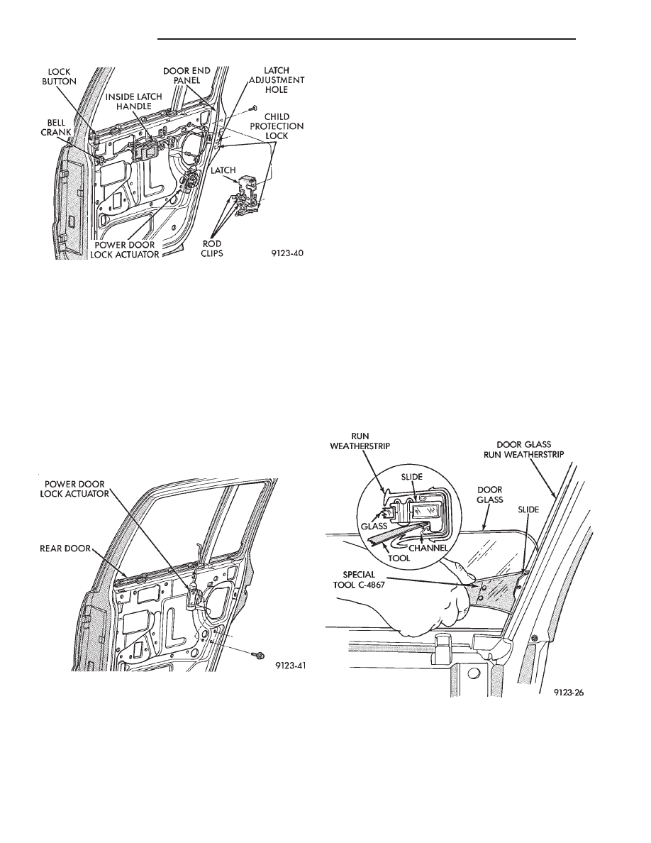
REAR POWER DOOR LOCK ACTUATOR
REMOVAL (FIG. 24)
(1) Remove door trim panel, silencer pad, and wa-
ter shield.
(2) Raise door glass to full up position.
(3) Remove door speaker, if equipped.
(4) Disconnect actuator rod from door latch assem-
bly.
(5) Remove screws holding power lock actuator to
inner door panel and separate from door.
INSTALLATION
Reverse the preceding operation.
REAR DOOR GLASS
REMOVAL (FIG. 25)
(1) Remove door trim panel and water shield.
(2) Position door glass half way up in door glass
opening.
(3) Pull upward firmly at the front upper corner of
glass to disengage lower glass guide from run chan-
nel.
(4) Insert door glass removal tool C-4867 between
the glass slide and division run channel retaining lip
at approximately 50 mm (2 in.) down from top rear-
ward corner of glass. Push handle of tool toward
glass to open channel. Pull forward on the glass to
separate the slide from the channel.
(5) Position glass inboard of the division channel.
Pivot top of glass rearward between division channel
and inner door panel.
(6) Separate regulator lift arm roller from glass lift
channel or remove bolt from regulator track, with
power windows.
(7) Remove door glass through opening at top of
door.
INSTALLATION
(1) Lower door glass into opening at top of door.
(2) Insert window regulator lift arm roller into
glass lift channel or install bolt to regulator track,
with power windows.
(3) Push top of glass rearward to snap top slide
into division run channel.
(4) Push downward at front of glass to snap bottom
slide into channel.
(5) Install water shield and trim panel.
REAR DOOR BELT MOULDING AND
WEATHERSTRIP
REMOVAL
(1) Remove trim panel, silencer pad, and water
shield.
Fig. 23 Rear Door Latch Assembly—Typical
Fig. 24-Rear Power Lock Actuator—Typical
Fig. 25 Rear Door Glass
23 - 106
AP-BODY
Ä