Chrysler Le Baron, Dodge Dynasty, Plymouth Acclaim. Manual - part 56
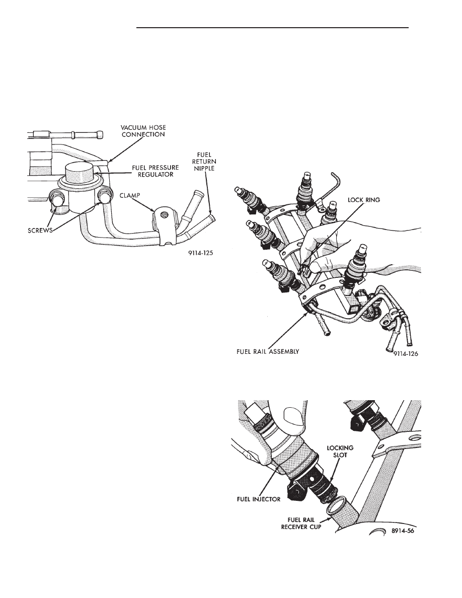
(3) Loosen fuel return hose clamp and remove fuel
return hose from nipple.
(4) Remove vacuum hose from fuel pressure regu-
lator. (Fig. 13).
(5) Remove screw holding fuel return tube to the
intake manifold.
(6) Remove fuel pressure regulator screws. Remove
fuel pressure regulator from engine.
INSTALLATION
(1) Lubricate O-ring on fuel pressure regulator
with clean 30 weight engine oil.
(2) Install fuel pressure regulator into fuel rail.
Tighten screws to 10 N
Im (90 in. lbs.) torque.
(3) Install screw holding fuel return tube clamp in
place. Tighten screw to 10 N
Im (95 in. lbs.) torque.
(4) Connect vacuum hose to fuel pressure regula-
tor.
(5) Connect fuel return hose to fuel return tube.
Tighten hose clamp to 1 N
Im (10 in. lbs.) torque.
(6) Connect negative battery cable.
CAUTION: When using the ASD Fuel System Test,
the Auto Shutdown (ASD) Relay remains energized
for either 7 minutes, until the test is stopped, or un-
til the ignition switch is turned to the Off position.
(7) With the ignition key in ON position, access
the DRBII scan tool’s ASD Fuel System Test to pres-
surize the fuel system. Check for leaks.
FUEL INJECTORS
WARNING: THE 3.0L MPI FUEL SYSTEM IS UNDER
A CONSTANT PRESSURE OF APPROXIMATELY 330
KPA (48 PSI). PERFORM FUEL PRESSURE RE-
LEASE
PROCEDURE
BEFORE
SERVICING
THE
FUEL INJECTORS.
REMOVAL
(1) Perform the Fuel Pressure Release Procedure.
(2) Disconnect negative cable from battery.
The fuel rail must be removed first to service the
injectors. Refer to Fuel Injector Rail Assembly Re-
moval in this section.
(3) Label each injector connector with its cylinder
number. Disconnect electrical connector from injec-
tor.
(4) Position fuel rail assembly so that the fuel in-
jectors are easily accessible.
(5) Remove injector clip from fuel rail and injector
(Fig. 14).
(6) Pull injector straight out of fuel rail receiver
cup (Fig. 15).
Fig. 13 Fuel Pressure Regulator
Fig. 14 Fuel Injector and Rail
Fig. 15 Servicing Fuel Injector
14 - 142
FUEL SYSTEMS
Ä