Chrysler Le Baron, Dodge Dynasty, Plymouth Acclaim. Manual - part 37
2.5L FLEXIBLE FUEL MULTI-PORT FUEL INJECTION—GENERAL DIAGNOSIS
INDEX
page
page
Fuel System Diagram
. . . . . . . . . . . . . . . . . . . . . 66
Visual Inspection
. . . . . . . . . . . . . . . . . . . . . . . . . 66
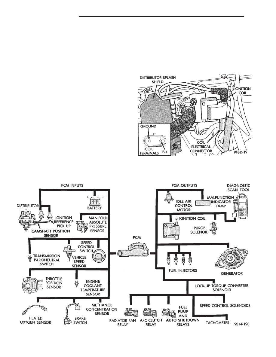
FUEL SYSTEM DIAGRAM
Refer to the Component Identification portion of
this section for a more complete description of the
components shown in Figure 1.
VISUAL INSPECTION
Perform a visual inspection for loose, disconnected,
or misrouted wires and hoses before diagnosing or
servicing the fuel injection system. A visual check
helps save unnecessary test and diagnostic time. A
thorough visual inspection includes the following
checks:
(1) Check Ignition Coil Electrical Connections (Fig.
2).
(2) Verify the electrical connector is attached to
the Canister Purge Solenoid (Fig. 3). Check the vac-
uum connections at the solenoid and canister.
(3) Verify the electrical connector is attached to
the MAP sensor (Fig. 4). Inspect the MAP sensor
vacuum hose for damage and leaks.
(4) Verify generator wiring and belt are correctly
installed and tightened.
Fig. 1 Flexible Fuel MPI Components
Fig. 2 Ignition Coil Electrical Connection
14 - 66
FUEL SYSTEMS
Ä