Daewoo Musso. Manual - part 321


  Index      Daewoo     Daewoo Musso - service repair manual


Search            


Content   ..  319  320  321  322   ..


Daewoo Musso. Manual - part 321


MANUAL & SEMIAUTO-HVAC  7B/C-19

Removal & Installation Procedure

1. Disconnect the negative(-) terminal from the battery.

2. Discharge refrigerant from the system.

Notice

By connecting a manifold gauge connection hose to High/
Low pressure line, discharge the refrigerant.

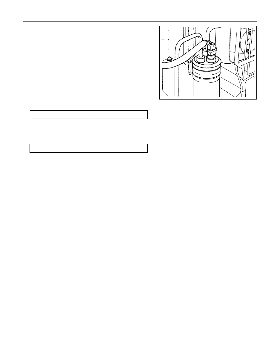
3. Disconnect the inlet and outlet pipes of receiver drier.

Notice

When installing, check the O-ring and apply the compressor
oil.

Installation Notice

4. Remove the bracket bolt and then remove the receiver drier.

Installation Notice

Tightening Torque

4 - 6 Nm

5. Installation should follow the removal procedure in the

reverse order.

Tightening Torque

5 - 8 Nm

7B/C-20  MANUAL & SEMIAUTO-HVAC

1 Condenser
2 Receiver Drier

3 Bracket

Removal & Installation Procedure

1. Disconnect the dual pressure switch connector from the

receiver drier.

2. Discharge refrigerant from the system.

3. Remove the high pressure pipe from the inlet / outlet of

receiver drier.

4. Remove the bracket bolts and remove the receiver drier.

5. Installation should follow the removal procedure in the

reverse order.

Gasoline Engine

MANUAL & SEMIAUTO-HVAC  7B/C-21

COMPRESSOR

Preceding Work : Removal of the poly V-belt

Diesel Engine

1 Low Pressure Pipe
2 High Pressure Pipe

3 Compressor Bracket
4 Compressor

7B/C-22  MANUAL & SEMIAUTO-HVAC

Removal & Installation Procedure

1. Disconnect the negative(-) terminal from the battery.

2. Discharge refrigerant from the system.

Notice

By connecting a manifold gauge connection hose to High/
Low pressure line, discharge the refrigerant.

3. Disconnect the high / low pressure pipe and wire connectors.

Installation Notice

Notice

Before tightening, apply the compressor oil to O-ring.

Tightening Torque

20 - 30 Nm

4. Remove the mounting bolt from the compressor bracket

and remove compressor assembly.

Notice

Place the removed compressor in vertical position.

Installation Notice

5. Installation should follow the removal procedure in the

reverse order.

Tightening Torque

21 - 26 Nm


Content   ..  319  320  321  322   ..