Daewoo Musso. Manual - part 250


  Index      Daewoo     Daewoo Musso - service repair manual


Search            


Content   ..  248  249  250  251   ..


Daewoo Musso. Manual - part 250


5A-32  AUTOMATIC TRANSMISSION

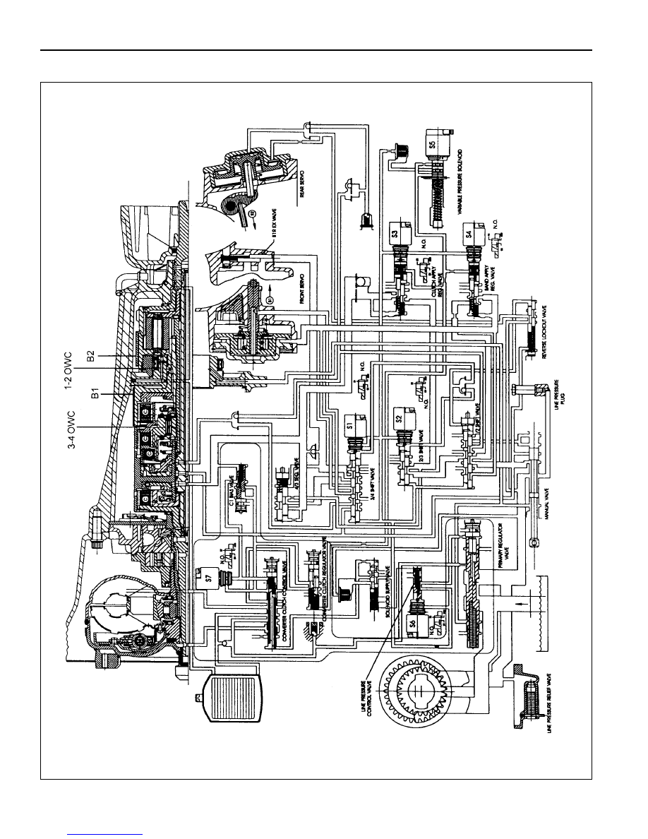
Figure 3.7 - Hydraulic Control Circuit

AUTOMATIC TRANSMISSION  5A-33

Figure 3.8 - Valve Body

Figure 3.9 - Pump Cover

Valve Body

Figure 3.8 depicts the valve body as a unit as viewed from the
transmission sump. Figure 3.9 depicts the pump cover.

5A-34  AUTOMATIC TRANSMISSION

Figure 3.10 - Manual Valve

1-2 Shift Valve

The 1-2 shift valve (refer to figure 3.11) is a two position valve that must be switched to the (2,3,4) position in order to
get any forward gear other than first gear. It is used for all 1-2 and 2-1 gearshifts.

The switching of this valve is achieved by using S1 and/or S2.

During a 1-2 gearshift drive oil from the manual valve passes through to the second gear circuit. During a 2-1
gearshift the band apply feed oil is allowed to exhaust via the 1-2 shift valve.

The 1-2 shift valve works in conjunction with the 3-4 shift valve (described below) to disengage  the C4 clutch in first
gear, and engage C4 in second gear. When Manual 1 is selected the C4 clutch and rear band (B2) are engaged.

Figure 3.11 - 1-2 Shift Valve

Manual Valve

The manual valve (refer to figure 3.10) is connected to the vehicle selector mechanism and controls the flow of oil to
the forward and reverse circuits. The manual valve function is identical in all forward gear positions except that in the
Manual 1 position an additional supply of oil is directed to the 1-2 shift valve for application of the rear band and the
C4 overrun clutch.

AUTOMATIC TRANSMISSION  5A-35

2-3 Shift Valve

The 2-3 shift valve (refer to figure 3.12) is a two position valve. It is used on all 2-3 and 3-2 gearshifts.

The switching of this valve is achieved by S2 which is located at the end of the valve spool.

When in the (1,2) position, second gear oil from the 1-2 shift valve is prevented from entering the third gear circuit.
When the valve is moved to the (3,4) position, oil from the second gear circuit is routed to the third gear circuit and the
transmission changes to third gear.

Figure 3.12 - 2-3 Shift Valve

3-4 Shift Valve

The 3-4 shift valve (refer to figure 3,13) is a two position valve. It is used for all 3-4 and 4-3 gearshifts.

The switching of this valve is achieved by S1 which is located at the end of the valve spool.

During a 3-4 gearshift the 3-4 shift valve:

l

Exhausts the front band release circuit (B 1R) thereby allowing the application of the front band (B1).

l

Connects the inner apply area of the front servo (B 1AI) to the band apply feed circuit (BAF) thus allowing
greater apply forces to the front band.

l

Exhausts the overrun clutch circuit (OC) which allows the C4 clutch to disengage.

During a 4-3 gearshift, the C4 clutch is engaged and the front band (B1) is released. These actions are sequenced
by the 4-3 sequence valve (described below).

The 3-4 shift valve also switches during 1-2 and 2-1 gearshifts (see 1-2 shift valve above) where its function is to
apply the overrun clutch (C4) in second gear but to release it in first gear. Note that the C4 clutch is applied in Manual
1 by virtue of the manual valve and the 1-2 shift valve (as described in the 1-2 shift valve section).

Figure 3.13 - 3-4 Shift Valve


Content   ..  248  249  250  251   ..