Daewoo Musso. Manual - part 118
 

  Index      Daewoo     Daewoo Musso - service repair manual


Search            


Content   ..  116  117  118  119   ..


Daewoo Musso. Manual - part 118


OM600 ENGINE MECHANICAL  1B3-179

Measurement Procedure

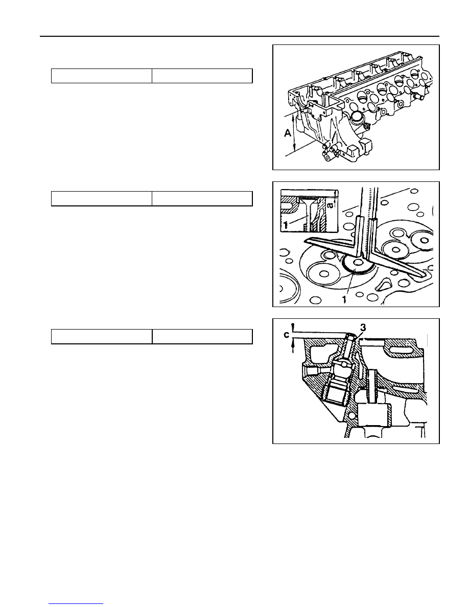
1. Measure height ‘A’.

Limit

 142.5 mm

Notice

If the height is less than 142.5mm, replace the cylinder head.

2. Insert the valve (1) and measure valve arrears ‘a’.

Valve Arrears ‘a’

0.1 - 0.7 mm

Notice

If out of standard, machine the valve seat.

3. Install the prechamber and measure protrusion ‘C’.

Protrusion ‘C’

 7.6 - 8.1mm

4. Assemble the engine and check the valve timing.

1B3-180  OM600 ENGINE MECHANICAL

REPLACEMENT OF CRANKCASE CORE PLUG

  Left

  Right

Core plug .......................................................

f

 34mm

OM661LA - 2EA
OM662LA - 3EA

Core plug .......................................................

f

 34mm

OM661LA - 2EA
OM662LA - 3EA

Core plug .......................................................

f

 17mm

OM661LA - 1EA
OM662LA - 1EA

Core plug .......................................................

f

 34mm

OM661LA - 1EA
OM662LA - 1EA

  Left

  Right

OM600 ENGINE MECHANICAL  1B3-181

Tools Required

102 589 00 15 00  Drift

102 589 12 15 00  Drift

Replacement Procedure

1. Completely drain the coolant.

2. Remove any parts which impede access.

(Example : transmission, injection pump)

3. Place the screwdriver to the deepdrawn edge of the core

plug and pull forward and then rotate 90°.

4. Pull out the core plug with pliers.

5. Thoroughly clean the sealing surface and apply Loctite 241.

6. Install the new core plug by using a drift.

Drift 102 589 00 15 00 (F34)
Drift 102 589 12 15 00 (F17)

7. Install the removed parts and fill the coolant.

Notice

The adhesive must be allowed to harden for about 45
minutes before filling of coolant.

8. Warm up the engine and check the coolant for leaks.

1B3-182  OM600 ENGINE MECHANICAL

Service Data

Height ‘Y’

Permissible unevenness of contacting surface

Permissible roughness upper contacting surface

Permissible variation of parallelism of crankcase upper

surface to lower surface in longitudinal direction

Piston protrusion at TDC to crankcase upper surface

In longitudinal direction (B)

In transverse direction (C)

Min. 299.62 mm

0.06 mm

0.06 mm

0.0006 - 0.0016 mm

0.05 mm

0.965 mm

0.735 mm

Max.

Min.

FACING CRANKCASE CONTACTING SURFACE

1 Crankcase
2 Crankcase Contacting Surface

Y Height (crankcase upper surface - crankcase

lower surface)

B Longitudinal Direction

C Transverse Direction

H Chamfer Height

b Chamfer Angle


Content   ..  116  117  118  119   ..