Daewoo Musso. Manual - part 33
1B1-68 M162 ENGINE MECHANICAL
Tools Required
111 589 01 59 00
Supporting Bar
111 589 18 61 00
Lever Pusher
111 589 25 63 00
Thrust Piece
116 589 06 63 00
Magnetic Finger
Removal & Installation Procedure
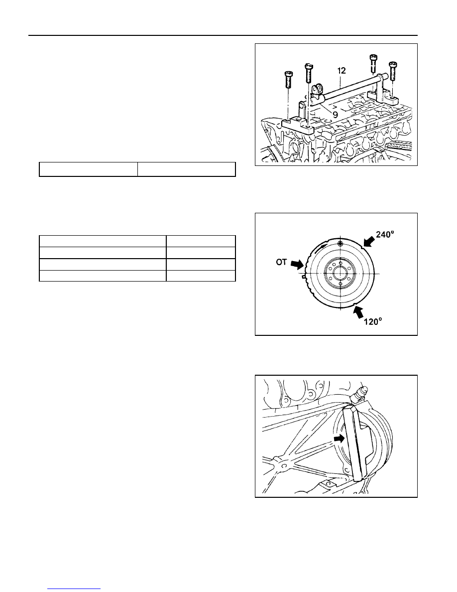
1. Place the supporting bar (12) and the slide (9) at the
camshaft bearing cap (Nos 1 & 7/8&14) and tighten them
with the bearing cap bolt.
Installation Notice
2. Turn the crankshaft to position the each cylinder piston at
TDC.
5. Install the engine lock to the ring gear to prevent the
crankshaft from rotating.
6. Blow up with compressed air.
Notice
l
Remove the valve spring only at TDC.
l
Always rotate the crankshaft by holding the chain to
prevent from timing chain damage and tangling, and for
smooth rotation.
3. Remove the valve tappet (1) using the magnetic finger.
4. Install the leakage tester connecting hose to the spark plug
hole.
Supporting Bar 111 589 01 59 00
Tightening Torque
22.5 - 27.5 Nm
Mark on The Vibration Damper
OT
120°
240°
Cylinder
1, 6
2, 5
3, 4