Daewoo Matiz (2003 year). Manual - part 248


  Index      Daewoo     Daewoo Matiz - service repair manual 2003 year


Search            


Content   ..  246  247  248  249   ..


Daewoo Matiz (2003 year). Manual - part 248


9E – 26  INSTRUMENT/DRIVER INFORMATION

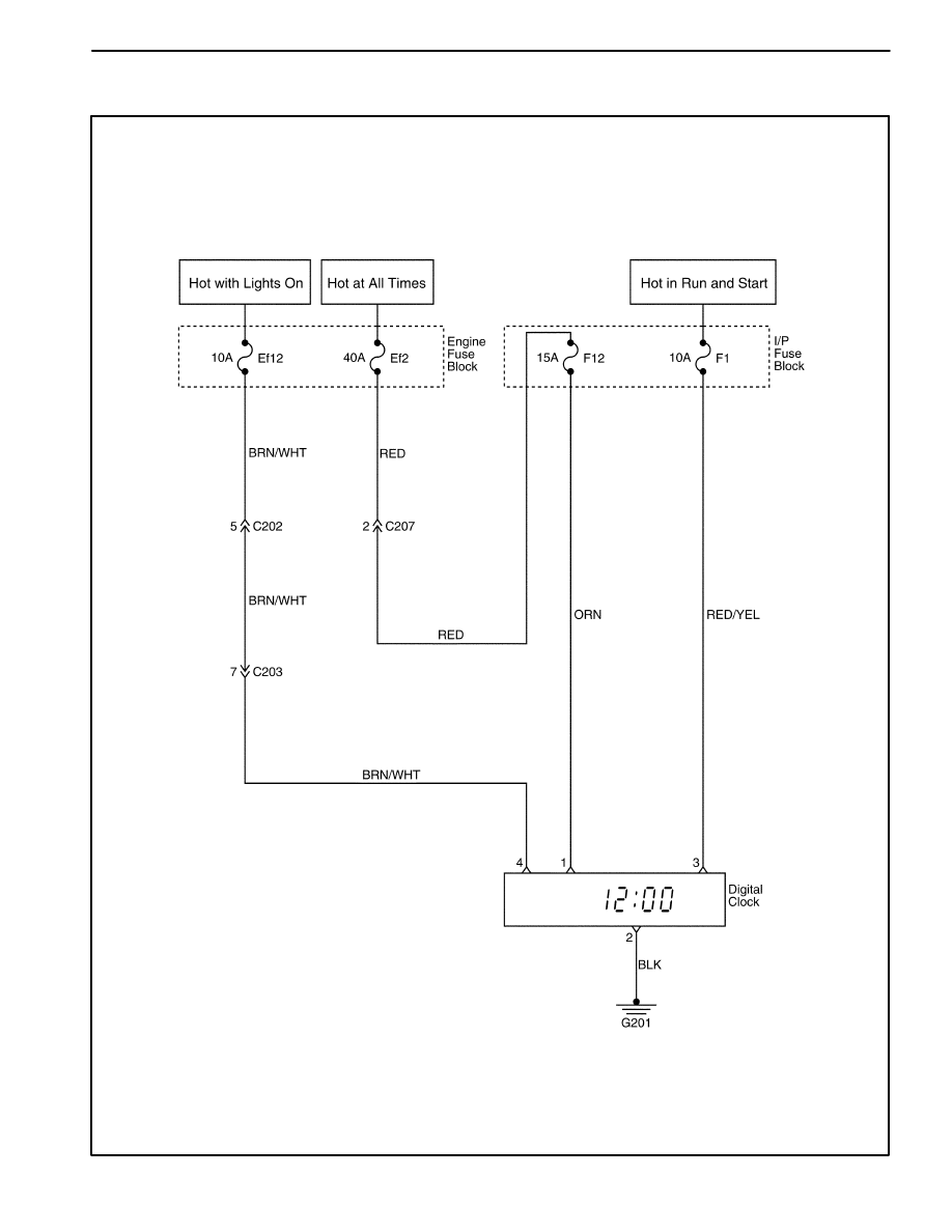
DIGITAL CLOCK

D19B203B
SECTION 9F

AUDIO SYSTEMS

CAUTION: Disconnect the negative battery cable before removing or installing any electrical unit or when a
tool or equipment could easily come in contact with exposed electrical terminals. Disconnecting this cable
will help prevent personal injury and damage to the vehicle. The ignition must also be in B unless otherwise
noted.

TABLE OF CONTENTS

Description and Operation

9F-2

. . . . . . . . . . . . . . . . . . 

Stereo Cassette AM/FM Radio with CD Changer 

   and RDS/Audio Security System

9F-2

. . . . . . . . . . . . . 

Front and Rear Speakers

9F-2

. . . . . . . . . . . . . . . . . . . 

Roof Antenna

9F-2

. . . . . . . . . . . . . . . . . . . . . . . . . . . . . 

Tape Player and Cassette Care

9F-2

. . . . . . . . . . . . . 

Compact Disc Care

9F-2

. . . . . . . . . . . . . . . . . . . . . . . . 

Component Locator

9F-3

. . . . . . . . . . . . . . . . . . . . . . . . 

Audio Systems

9F-3

. . . . . . . . . . . . . . . . . . . . . . . . . . . . 

Diagnostic Information and Procedures

9F-4

. . . . . 

Audio System

9F-4

. . . . . . . . . . . . . . . . . . . . . . . . . . . . . 

Repair Instructions

9F-6

. . . . . . . . . . . . . . . . . . . . . . . . . 

On–Vehicle Service

9F-6

. . . . . . . . . . . . . . . . . . . . . . . . . . 

Audio System

9F-6

. . . . . . . . . . . . . . . . . . . . . . . . . . . . . 

CD Changer

9F-6

. . . . . . . . . . . . . . . . . . . . . . . . . . . . . . 

Front Speakers

9F-8

. . . . . . . . . . . . . . . . . . . . . . . . . . . 

Front Speaker Covers

9F-9

. . . . . . . . . . . . . . . . . . . . . . 

Rear Speakers

9F-9

. . . . . . . . . . . . . . . . . . . . . . . . . . . . 

Roof Antenna

9F-10

. . . . . . . . . . . . . . . . . . . . . . . . . . . . 

Specifications

9F-11

. . . . . . . . . . . . . . . . . . . . . . . . . . . . 

Fastener Tightening Specifications

9F-11

. . . . . . . . . . 

Schematic and Routing Diagrams

9F-12

. . . . . . . . . . 

Audio System Circuit

9F-12

. . . . . . . . . . . . . . . . . . . . . . 

9F – 2  AUDIO SYSTEMS

DESCRIPTION AND OPERATION

STEREO CASSETTE AM/FM RADIO
WITH CD CHANGER AND
RDS/AUDIO SECURITY SYSTEM

The stereo digital logic cassette AM/FM radio with elec-
tronic tape ejection and the stereo digital logic cassette
AM/FM radio with a CD changer located under the front
seat (LH) are optional equipment.

The radio data system (RDS) uses a single button to se-
lect a specific radio station once it is set to the listener’s
preference.

The audio security system is activated whenever the au-
dio system circuit is disconnected from the battery. A
four-digit security code must be entered in order for the
audio system to be functional once again. The security
code is stamped on a card located in the vehicle (usually
in the glove box). One of the following security code en-
tering procedures can be followed.

With RDS

1. With the ignition switch in the I or II position, turn the

radio ON. At this time, “CODE” will be shown on the
radio display.

2. Press the P-UP button until the correct first digit is

shown on the display.

3. Press the P-DN button to move over to the second

digit and then press P-UP once again to enter the cor-
rect second digit.

4. Use steps two and three to enter the third and fourth

digits using the same method.

5. After entering the correct four-digit security code,

press the TP button. “CODE OK” will briefly appear
on the radio display, and the system is ready for use.

Wrong Code

If the wrong code is entered, “ERROR 1” will appear on
the display. After this, “CODE” will appear once again,
and the correct security code can be entered. The time

between each new coding attempt is doubled; a total of
ten coding attempts can be made.

FRONT AND REAR SPEAKERS

All audio systems use four speakers: two speakers
mounted in the front doors and two speakers mounted in
the rear parcel side shelf.

ROOF ANTENNA

Roof antenna is located on the roof and is designed to
separate the antenna pole from the antenna base. The
antenna pole should be removed to prevent the painting
damage before washing the vehicle. The roof antenna
cannot be adjusted.

TAPE PLAYER AND CASSETTE CARE

The head and the capstan are the two parts of the tape
player that should be cleaned. This service should be
performed every 100 hours of cassette operation.

In order to clean the head and the capstan, use a cotton
swab dipped in rubbing alcohol.

A cassette cleaning kit may also be used to clean the
head and the capstan. Follow the cleaning kit instruc-
tions to clean the tape player.

Do not touch the tape head with magnetized tools. If the
head becomes magnetized, it will degrade cassettes
played in the player. No service is performed on the cas-
settes. The cassette manufacturer handles warranties
of the cassettes. Store cassettes away from extreme
heat and direct sunlight.

COMPACT DISC CARE

Handle discs carefully. Store the discs in protective
cases away from the sun, heat, and dust. If the surface
is soiled, dampen a clean, soft cloth in a solution of mild
neutral detergent and wipe the disc clean. Mini discs
(about 3 inches in diameter), will not eject and should
not be used.

AUDIO SYSTEMS  9F – 3

COMPONENT LOCATOR

AUDIO SYSTEMS

D19D401B

1. Roof Antenna Assembly
2. Roof Antenna Pole
3. Roof Antenna Base
4. Roof Antenna Frame
5. Roof Antenna Cable
6. Front Speaker

7. Rear Speaker
8. Audio
9. CD Changer Cable

10. CD Changer Bracket

11. CD Changer Magazine

12. CD Changer


Content   ..  246  247  248  249   ..