Daewoo Matiz (2003 year). Manual - part 244
 

  Index      Daewoo     Daewoo Matiz - service repair manual 2003 year


Search            


Content   ..  242  243  244  245   ..


Daewoo Matiz (2003 year). Manual - part 244


9E – 10 INSTRUMENTATION/DRIVER INFORMATION

D109B508

Installation Procedure

1. Install the vents to the instrument cluster trim panel

with the screws.

2. Install the instrument cluster trim panel. Refer to “In-

strument Cluster Trim Panel” in this section.

D109B511

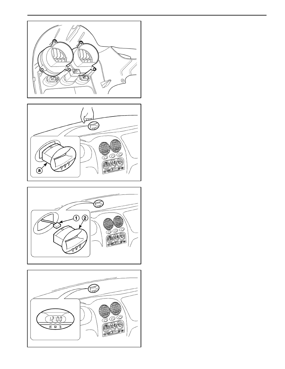
DIGITAL CLOCK

(Left–Hand Drive Shown, Right–Hand
Drive Similar)

Removal Procedure

1. Disconnect the negative battery cable.

2. Pry off the defroster grille.

3. Unlock the locking of the digital clock.

a. Digital clock.

D109B512

4. Remove the digital clock from the instrument panel.

D

Disconnect the electrical connector (1).

D

Remove the digital clock (2).

D109B513

Installation Procedure

1. Connect the electrical connector.

2. Install the digital clock to the instrument panel.

3. Connect the negative battery cable.

4. Set the clock.

INSTRUMENTATION/DRIVER INFORMATION 9E – 11

D109B509

GLOVE BOX

(Left–Hand Drive Shown, Right–Hand
Drive Similar)

Removal Procedure

1. Remove the hinge pins at the base of the glove box.

D109B510

2. Remove the glove box from the instrument panel.

D109B509

Installation Procedure

1. Install the glove box to the instrument panel with the

hinge pins.

D19B514A

INSTRUMENT CLUSTER

Removal Procedure

1. Disconnect the negative battery cable.

2. Remove the instrument cluster trim panel from the in-

strument panel. Refer to “Instrument Cluster Trim
Panel” in this section.

3. Remove the instrument cluster assembly from the in-

strument panel.

D

Remove the screws (1).

D

Disconnect the electrical connector and the
speedometer cable (2).

D

Remove the instrument cluster (3).

9E – 12 INSTRUMENTATION/DRIVER INFORMATION

D19B515A

Installation Procedure

 1. Connect the electrical connector and the speedom-

eter cable.

 2. Install the instrument cluster assembly to instrument

panel with screws.

 3. Install the instrument cluster trim panel to the instru-

ment panel. Refer to “Instrument Cluster Trim Pan-
el” in this section.

 4. Connect the negative battery cable.

D109B516

INSTRUMENT PANEL

(Left–Hand Drive Shown, Right–Hand
Drive Similar)

Removal Procedure

 1. Disconnect the negative battery cable.
 2. Remove the driver’s airbag module from the steer-

ing wheel. Refer to Section 8B, Supplemental Inflat-
able Restraints (SIR)
 (For the vehicle equipped with
the airbag).

 3. Remove the steering wheel from the steering col-

umn. Refer to Section 6E, Steering Wheel and Col-
umn.

 4. Remove the steering column trim cover. Refer to

Section 6E, Steering Wheel and Column.

 5. Remove the signal lamp switch and the wiper

switch. Refer to Section 6E, Steering Wheel and
Column.

 6. Pry off the A–pillar trim panels. Refer to Section 9G,

Interior Trim.

 7. Remove the instrument cluster trim panel from the

instrument panel.

D

Remove the screws (1)

D

Using a flathead screwdriver, remove the instru-
ment cluster trim panel (2).

Notice: To prevent the instrument panel damage, cover
the flathead screwdriver with a soft cloth.

D109B517

 8. Remove the hood latch release lever from the in-

strument panel. Refer to Section 9R, Body Front
End.

 9. Remove the glove box assembly from the instru-

ment panel. Refer to “Glove Box” in this section.

10. Remove the passenger’s airbag module from the in-

strument panel. Refer to Section 8B, Supplemental
Inflatable Restraints (SIR)
 (For vehicle equipped
with the airbag).

11. Put aside the floor console after removing the

screws (1).

INSTRUMENTATION/DRIVER INFORMATION 9E – 13

D109B518

12. Remove the instrument cluster assembly. Refer to

“Instrument Cluster” in this section.

13. Remove the A/C controller from the instrument. Re-

fer to Section 7B, Manual Control Heating, Ventila-
tion, and Air Conditioning System.

14. Remove the audio system from the instrument pan-

el. Refer to Section 9F, Audio Systems.

15. Disconnect the cigar lighter connector.

16. Disconnect the ashtray lamp if equipped.

D109B519

17. Disconnect the ALDL connector.

D

Remove the screws (1).

D

Disconnect the ALDL connector (2).

D109B520

18. Remove the instrument trim panel assembly.

D

Remove the bolts after removing the caps (1).

D

Remove the screws on the side plate (2).

D

Remove the tie–bar retaining bolts on the lower
panel (3).

D

Remove the instrument trim panel assembly (4).

D109B521

Installation Procedure

 1. Install the instrument trim panel assembly with the

bolts and screws.

 2. Connect the ALDL connector with the screws.

 3. Connect the ashtray lamp if equipped with.

 4. Connect the cigar lighter connector.

 5. Install the audio system to the instrument panel. Re-

fer to Section 9F, Audio Systems.

 6. Install the A/C controller to the instrument panel.

Refer to Section 7B, Manual Control Heating, Ven-
tilation, and Air Conditioning System.


Content   ..  242  243  244  245   ..