Daewoo Matiz (2003 year). Manual - part 185
6E – 14 STEERING WHEEL AND COLUMN
D15A704A
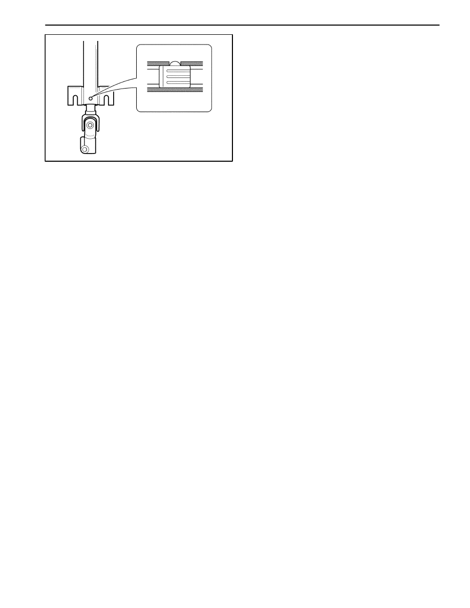
Assembly Procedure
Important: Position the alignment spacer on the lower
column shaft to install the spacer in the steering column
jacket easily.
1. Install the steering column shaft to the steering col-
umn.
D
Position the locking of the alignment spacer on the
groove of the steering column.
D
Install the washer.
D
Install the spring.
D
Install the washer.
D
Install the retaining ring.
2. Install the steering column to the vehicle. Refer to
“Steering Wheel” in this section.