Daewoo Korando. Manual - part 230
 

  Index      Daewoo     Daewoo Korando - service repair manual


Search            


Content   ..  228  229  230  231   ..


Daewoo Korando. Manual - part 230


POWER BOOSTER  4C-3

Removal & Installation Procedure

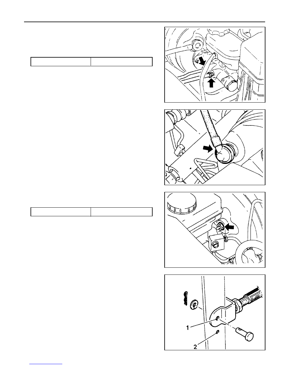
1. Remove the oil level sensor connector.

2. Remove the tube from the master cylinder.

Installation Notice

Notice

l

Be careful not to drop the oil when removing the tube.

l

If the oil is dropped, promptly sweep up.

3. Remove the booster vacuum hose.

Notice

l

Connect fully to the end of vacuum hose when installing.

4. Loosen the nut of master cylinder.

Installation Notice

5. Remove the clevis pin and disconnect the pedal and brake

booster push rod.

Notice

l

Install in the upper hole when PBR brake.

l

Connect the snap pin in the hole of clevis pin fully.

l

Apply the grease around the hole of clevis pin.

Tightening  Torque

14 - 22 Nm

Tightening  Torque

15 - 19 Nm

4C-4  POWER BOOSTER

6. Loosen the nut of booster and remove the booster from the

dash panel.

Installation Notice

Tightening  Torque

8 - 18 Nm

7. Installation should follow the removal procedure in the

reverse order.

8. Add the fluid and bleed.

9. If necessary, adjust the pedal height, pedal stroke and free

play.

POWER BOOSTER  4C-5

PEDAL STROKE INSPECTION

1. Start the engine and stop it after one or two minutes.

Depress the brake pedal several times.

If the pedal goes down furthest the first time, but gradually
rises after the second or third time, brake booster is normal.
If there is no change in pedal stroke, the brake booster is
abnormal.

2. Depress the brake pedal several times with engine stopped,

and depress the brake pedal and start the engine. If the
pedal goes down slightly, the booster is normal.

3. Depress the brake pedal with engine running, and stop it

with the pedal depressed. If there is no change in pedal
height during 30 sec., the booster is normal.

SECTION 4D

FRONT  DISC  BRAKES

TABLE OF CONTENTS

Specifications . . . . . . . . . . . . . . . . . . . . . . . .  4D-1

Fastener  Tightening  Specifications . . . . . . . . .  4D-1

Maintenance and Repair . . . . . . . . . . . . . . .  4D-2

On-Vehicle Service . . . . . . . . . . . . . . . . . . . . .  4D-2

SPECIFICATIONS

FASTENER TIGHTENING SPECIFICATIONS

Application

Caliper Mounting Bolt

Brake Hose Bolt & Nut

Caliper Bolt

N

·

·

·

·

·

m

85 - 105

25 - 35

22 - 34

Front Disc Brake . . . . . . . . . . . . . . . . . . . . . . .  4D-2

Unit Repair . . . . . . . . . . . . . . . . . . . . . . . . . .  4D-5

Front Disc Brake . . . . . . . . . . . . . . . . . . . . . . .  4D-5


Content   ..  228  229  230  231   ..