Daewoo Korando. Manual - part 158
 

  Index      Daewoo     Daewoo Korando - service repair manual


Search            


Content   ..  156  157  158  159   ..


Daewoo Korando. Manual - part 158


1F1-74  M162 ENGINE CONTROLS

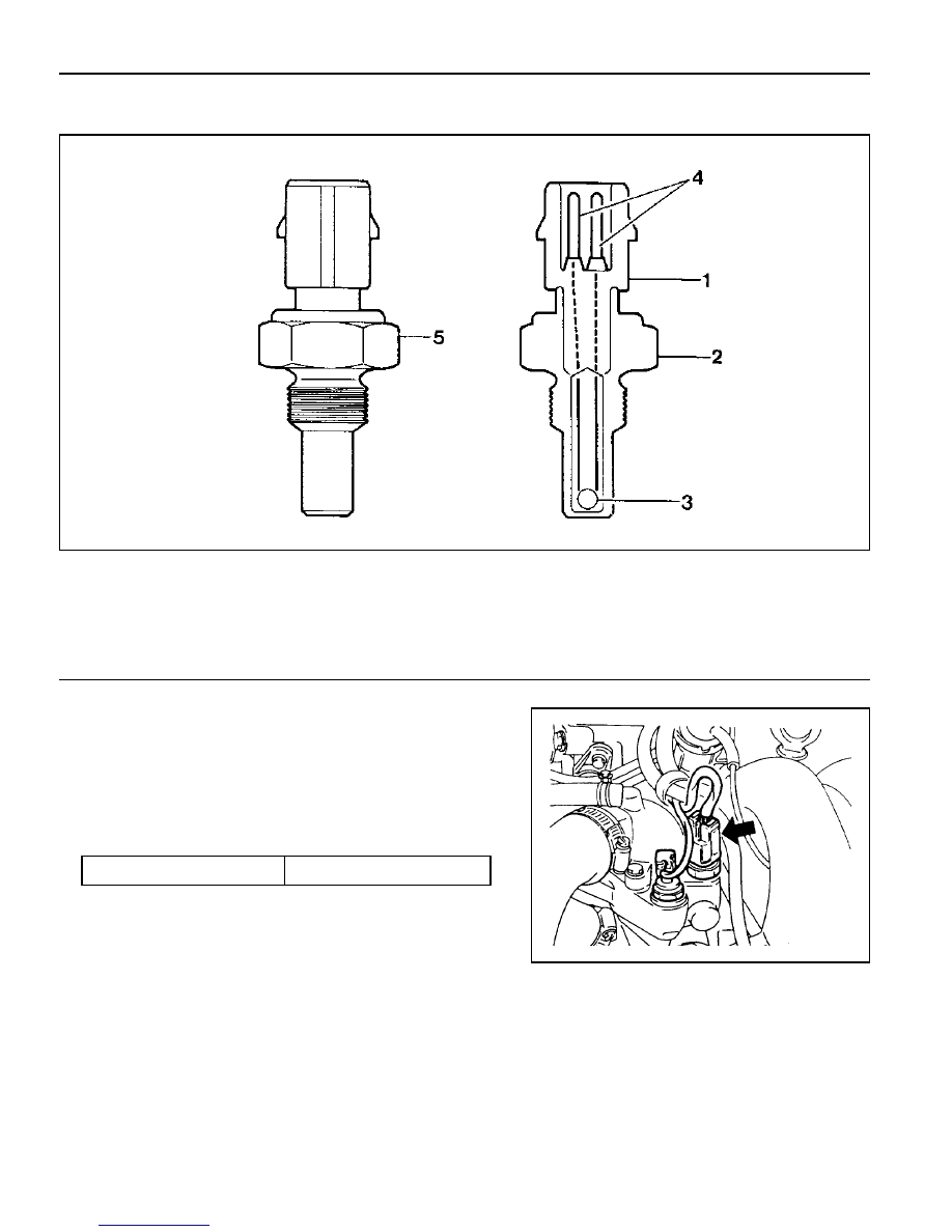
COOLANT TEMPERATURE SENSOR

1 Artificial Resin Housing
2 Metal Housing
3 NTC (negative temperature coefficient) Resistor

Removal & Installation Procedure

1. Remove the pressure by opening the pressure cap in the

coolant subtank.

2. Disconnect the connector and remove the coolant

temperature sensor.

Installation Notice

Replace the seals with new one.

3. Installation should follow the removal procedure in the

reverse order.

4. Check for leaks at each connections after starting the engine.

4 Connector
5 Coolant Temperature Sensor

Tightening  Torque

18 - 22 Nm

M162 ENGINE CONTROLS  1F1-75

2. Measure the resistance between the coolant temperature

sensor terminal No.1 and No.4 with the coolant temperature

sensor disconnected.

Inspection

1. Measure the coolant sensor input voltage between the ECU

terminal No.79 and No.78 while the ignition switch in "ON"
position.

Notice

Replace wiring and coolant temperature sensor if out of
specified value.

                                                             allowable error :

±

5%

        allowable error :

±

5%

Voltage (V)

3.57

1.22

0.78

Temperature (

°

C)

20

30

40

Resistance (

W

)

2,500

322

185

Temperature (

°

C)

20

30

40

1F1-76  M162 ENGINE CONTROLS

Service Data

Resistance characteristic curve according to the coolant
temperature

   Temperature(

°

C)

Resistance(W)        Voltage(V)         Temperature(

°

C)        Resistance(W)         Voltage(V)

            -40                          48,550                4.8991                    60                          594                     1.8632

            -30                          27,000                4.8214                    70                          434                     1.5132

            -20                          15,670                4.7001                    80                          322                     1.2179

            -10                           9,450                 4.5215                    90                          243                     0.9775

               0                           5,890                 4.4273                   100                         185                     0.7806

             10                           3,790                 3.9562                   110                         143                     0.6255

             20                           2,500                 3.5714                   120                         111.6                  0.5020

             30                           1,692                 3.1426                   130                          88.0                   0.4044

             40                           1,170                 2.6959                   140                          71.2                   0.3323

             50                             826                 2.2618                     -                               -                          -

M162 ENGINE CONTROLS  1F1-77

ACCELERATOR PEDAL MODULE

1 Accelerator Pedal
2 Accelerator Pedal Sensor
3 Bolts (2 Pieces) ....................................... 4-8 Nm

Removal and Installation Procedure

1. Disconnect the 6-pin connector (arrow).

2. Unscrew the 2 bolts (3) / 1 nut (6) and remove the pedal

and sensor assembly.

Installatoin Notice

Tightining  Torque

4 - 8 Nm

2. Installation should follow the removal procedure in the

reverse order.

4 6-Pin Connector
5 Kick Down Switch
6 Nut (1 Piece) ............................................ 4-8 Nm


Content   ..  156  157  158  159   ..